Teccor, Brand thyristors, 1 amp standard scrs – Littelfuse SxN1 Series User Manual
Page 6
214
Revised: 09/23/13
©2013 Littelfuse, Inc
Specifications are subject to change without notice.
Teccor
®
brand Thyristors
1 Amp Standard SCRs
Sx01E & SxN1 Series
Physical Specifications
Environmental Specifications
Test
Specifications and Conditions
AC Blocking
MIL-STD-750, M-1040, Cond A Applied
Peak AC voltage @ 125°C for 1008 hours
Temperature Cycling
MIL-STD-750, M-1051,
100 cycles; -40°C to +150°C; 15-min
dwell-time
Temperature/
Humidity
EIA / JEDEC, JESD22-A101
1008 hours; 320V - DC: 85°C; 85%
rel humidity
High Temp Storage
MIL-STD-750, M-1031,
1008 hours; 150°C
Low-Temp Storage
1008 hours; -40°C
Thermal Shock
MIL-STD-750, M-1056
10 cycles; 0°C to 100°C; 5-min dwell-
time at each temperature; 10 sec (max)
transfer time between temperature
Autoclave
EIA / JEDEC, JESD22-A102
168 hours (121°C at 2 ATMs) and
100% R/H
Resistance to
Solder Heat
MIL-STD-750 Method 2031
Solderability
ANSI/J-STD-002, category 3, Test A
Lead Bend
MIL-STD-750, M-2036 Cond E
Terminal Finish
100% Matte Tin-plated
Body Material
UL recognized epoxy meeting flammability
classification 94V-0
Lead Material
Copper Alloy
Design Considerations
Careful selection of the correct device for the application’s
operating parameters and environment will go a long way
toward extending the operating life of the Thyristor. Good
design practice should limit the maximum continuous
current through the main terminals to 75% of the device
rating. Other ways to ensure long life for a power discrete
semiconductor are proper heat sinking and selection of
voltage ratings for worst case conditions. Overheating,
overvoltage (including dv/dt), and surge currents are
the main killers of semiconductors. Correct mounting,
soldering, and forming of the leads also help protect
against component damage.
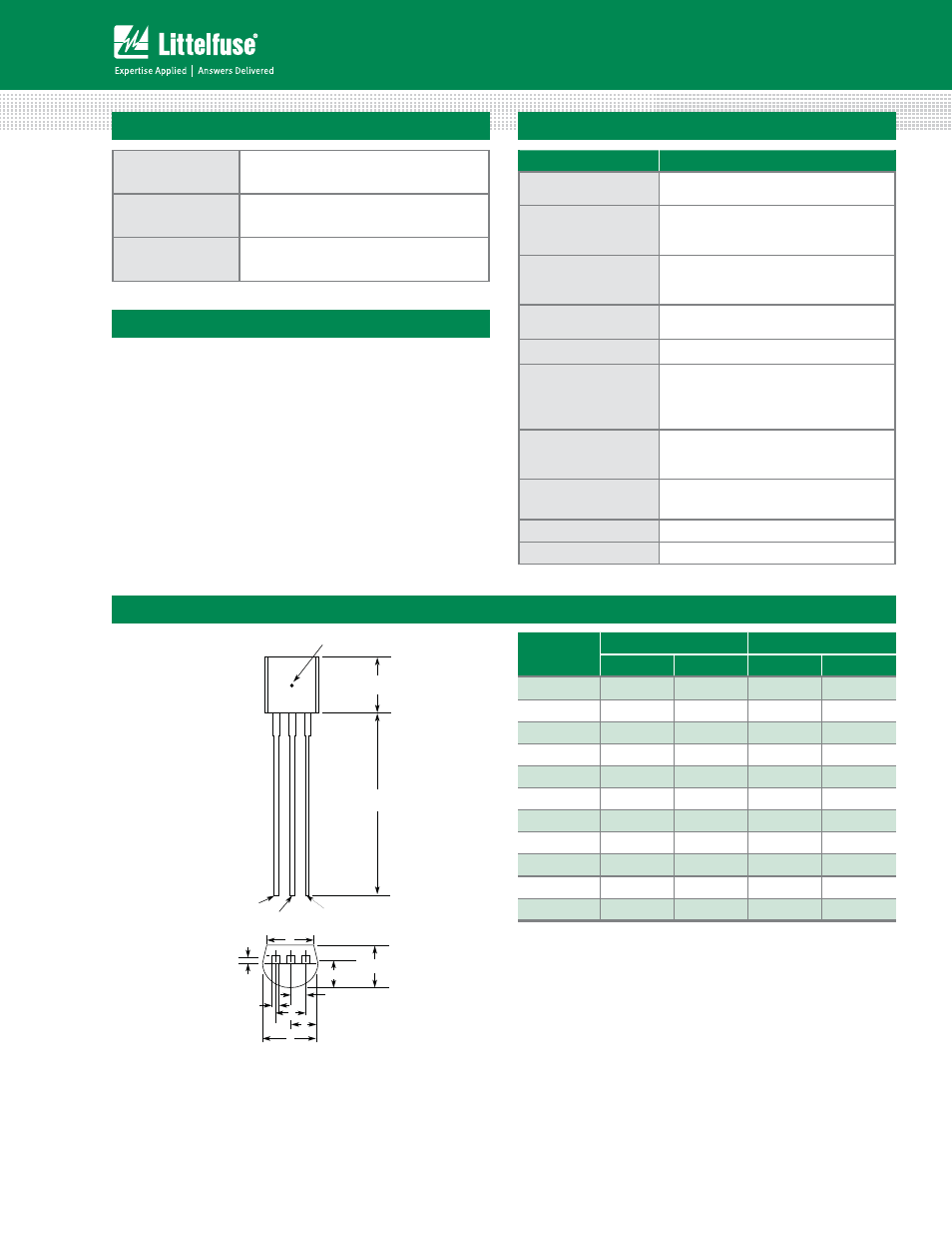
Dimensions – TO-92 (E Package)
Dimension
Inches
Millimeters
Min
Max
Min
Max
A
0.176
0.196
4.47
4.98
B
0.500
12.70
D
0.095
0.105
2.41
2.67
E
0.150
3.81
F
0.046
0.054
1.16
1.37
G
0.135
0.145
3.43
3.68
H
0.088
0.096
2.23
2.44
J
0.176
0.186
4.47
4.73
K
0.088
0.096
2.23
2.44
L
0.013
0.019
0.33
0.48
M
0.013
0.017
0.33
0.43
All leads insulated from case. Case is electrically nonconductive.
A
B
T
C
Measuring Point
Gate
Anode
Cathode
E
H
G
F
D
K
J
L
M