Teccor, Brand thyristors, 1 amp standard scrs – Littelfuse SxN1 Series User Manual
Page 4
212
Revised: 09/23/13
©2013 Littelfuse, Inc
Specifications are subject to change without notice.
Teccor
®
brand Thyristors
1 Amp Standard SCRs
Sx01E & SxN1 Series
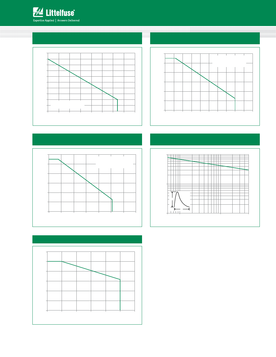
Figure 7: Maximum Allowable Case Temperature
vs. Average On-State Current
Figure 8: Maximum Allowable Ambient Temperature
vs. RMS On-State Current
Figure 9: Maximum Allowable Ambient Temperature
vs. Average On-State Current
80
85
90
95
100
105
110
115
120
125
130
0.0
0.1
0.2
0.3
0.4
0.5
0.6
0.7
0.8
Average On-State Current [I
T(AVE)
] - Amps
M
a
xi
m
u
m
A
ll
o
w
a
b
le C
ase T
e
m
p
er
at
u
re (
T
C
) - °
C
CURRENT WAVEFORM: Sinusoidal
LOAD: Resistive or Inductive
CONDUCTION ANGLE: 180°
0
20
40
60
80
100
120
0.0
0.1
0.2
0.3
0.4
0.5
0.6
0.7
0.8
0.9
1.0
RMS On-State Current [I
T(RMS)
] - Amps
Maximum Allowable Ambient Temperature (T
A
) - °C
CURRENT WAVEFORM: Sinusoidal
LOAD: Resistive or Inductive
CONDUCTION ANGLE: 180°
FREE AIR RATING
0
20
40
60
80
100
120
0.0
0.1
0.2
0.3
0.4
0.5
0.6
0.7
Average On-State Current [I
T(AVE)
] - Amps
M
axi
m
u
m
A
ll
o
w
a
b
le A
m
b
ien
t T
e
m
p
er
at
u
re
(T
A
) - °
C
CURRENT WAVEFORM: Sinusoidal
LOAD: Resistive or Inductive
CONDUCTION ANGLE: 180°
FREE AIR RATING
Figure 11: Peak Capacitor Discharge Current Derating
Figure 10: Peak Capacitor Discharge Current
1
10
100
0.5
1.0
10.0
50.0
Pulse Current Duration (t
W
) - ms
Peak Discharge Current (I
TM
) - Amps
I
TRM
t
W
0.0
0.2
0.4
0.6
0.8
1.0
1.2
0
25
50
75
100
125
150
Case Temperature (T
C
) - °C
Normalized Peak Current