Teccor, Brand thyristors, 4 amp sensitive scrs – Littelfuse Sxx04xSx Series User Manual
Page 5
239
Revised: 09/23/13
©2013 Littelfuse, Inc
Specifications are subject to change without notice.
Teccor
®
brand Thyristors
4 Amp Sensitive SCRs
Sxx04xSx Series
0.1
1.0
10.0
100.0
1
10
100
1000
Sxx04VSy
Sxx04DSy
P
eak Sur
g
e
(Non-r
epetitiv
e)
On-stat
e Cur
rent (I
TSM
) –
Amps
Surge Current Duration -- Full Cycles
Figure 13: Surge Peak On-State Current vs. Number of Cycles
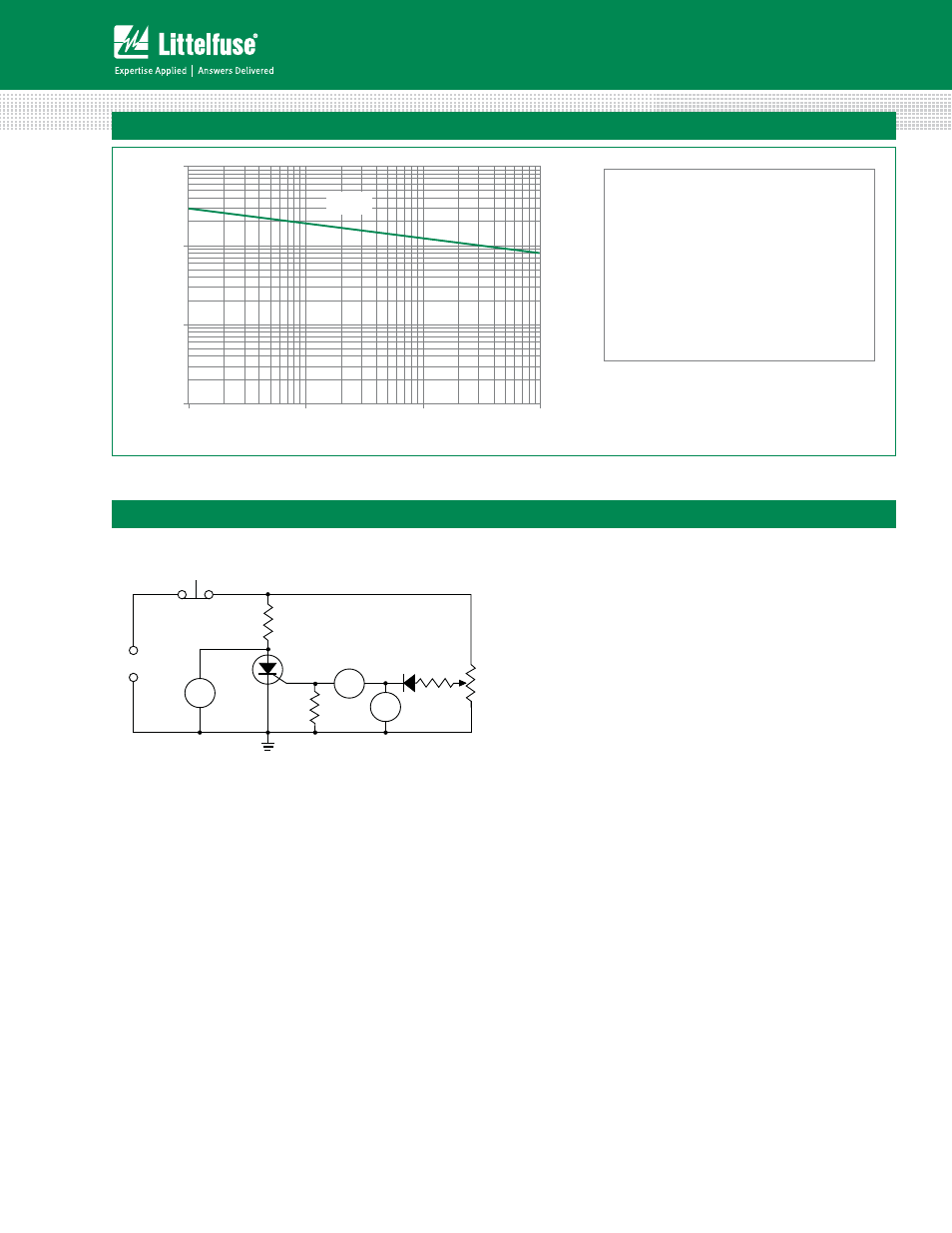
Figure 14: Simple Test Circuit for Gate Trigger Voltage and Current
SUPPLY FREQUENCY: 60 Hz Sinusoidal
LOAD: Resistive
RMS On-State Current: [I
T(RMS)
]: Maximum Rated
Value at Specified Case Temperature
Notes:
1. Gate control may be lost during and immediately
following surge current interval.
2. Overload may not be repeated until junction
temperature has returned to steady-state
rated value.
Note: V1 — 0 V to 10 V dc meter
V
GT
— 0 V to 1 V dc meter
I
G
— 0 mA to 1 mA dc milliammeter
R1 — 1 k potentiometer
To measure gate trigger voltage and current, raise gate
voltage (V
GT
) until meter reading V1 drops from 6 V to 1 V.
Gate trigger voltage is the reading on V
GT
just prior to V1
dropping. Gate trigger current I
GT
Can be computed from
the relationship
V
GT
I
GT
= I
G
- ____
Amps
1000
where I
G
is reading (in amperes) on meter just prior to V1
dropping
Note: I
GT
may turn out to be a negative quantity (trigger
current flows out from gate lead). If negative current
occurs, I
GT
value is not a valid reading. Remove 1 k resistor
and use I
G
as the more correct I
GT
value. This will occur on
12 μA gate products.
Reset
Normally-closed
Pushbutton
6V
DC
+
–
D.U.T.
100
R1
1 k
(1%)
100
I
GT
I
G
IN4001
V1
V
GT
Note: xx or z - voltage, y = sensitivity