Teccor, Brand thyristors, 4 amp sensitive scrs – Littelfuse Sxx04xSx Series User Manual
Page 4
238
Revised: 09/23/13
©2013 Littelfuse, Inc
Specifications are subject to change without notice.
Teccor
®
brand Thyristors
4 Amp Sensitive SCRs
Sxx04xSx Series
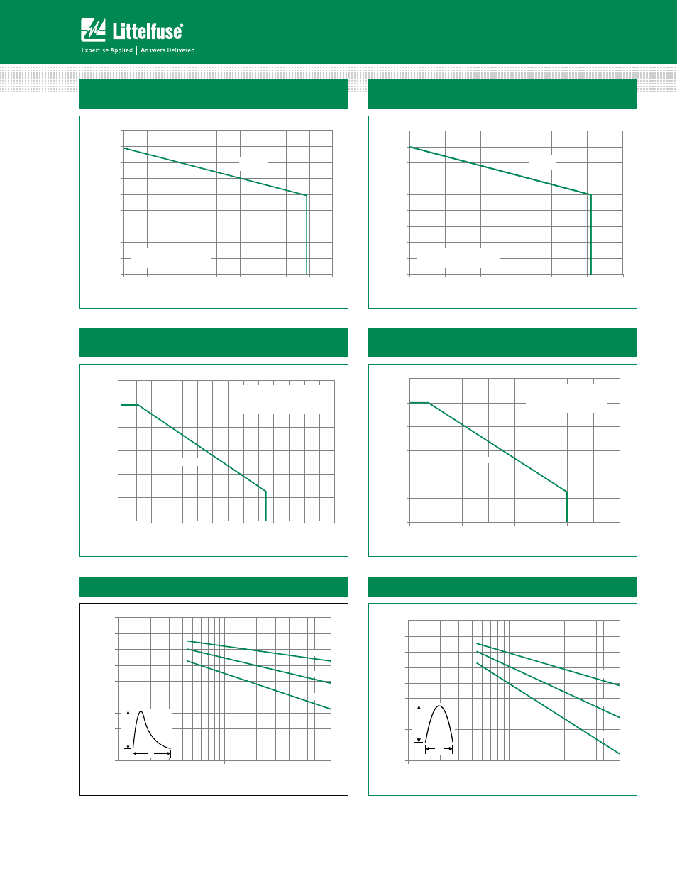
Figure 7: Maximum Allowable Case Temperature
vs. RMS On-State Current
Figure 8: Maximum Allowable Case Temperature
vs. Average On-State Current
Figure 9: Maximum Allowable Ambient Temperature
vs. RMS On-State Current
Figure 10: Maximum Allowable Ambient Temperature
vs. Average On-State Current
Note: xx = voltage, y = sensitivity
70
75
80
85
90
95
100
105
110
115
0.0
0.5
1.0
1.5
2.0
2.5
3.0
3.5
4.0
4.5
CURRENT WAVEFORM: Sinusoidal
LOAD: Resistive or Inductive
CONDUCTION ANGLE: 180°
Maximum Allo
w
able
Case
Temper
at
ur
e (T
C
) - °C
RMS On-State Current [I
T(RMS)
] - Amps
Sxx04VSy
Sxx04DSy
70
75
80
85
90
95
100
105
110
115
0.0
0.5
1.0
1.5
2.0
2.5
3.0
Maximum Allo
w
able
Case
Temper
at
ur
e (T
C
) - °C
Average On-State Current [I
T(AVE)
] - Amps
CURRENT WAVEFORM: Sinusoidal
LOAD: Resistive or Inductive
CONDUCTION ANGLE: 180°
Sxx04VSy
Sxx04DSy
0
20
40
60
80
100
120
0.0
0.2
0.4
0.6
0.8
1.0
1.2
1.4
CURRENT WAVEFORM: Sinusoidal
LOAD: Resistive or Inductive
CONDUCTION ANGLE: 180°
FREE AIR RATING
Maximum Allo
w
able Ambient
Temper
at
ur
e
(T
A
) -°C
RMS On-State Current [I
T(RMS)
] - Amps
Sxx04VSy
0
20
40
60
80
100
120
0.0
0.2
0.4
0.6
0.8
CURRENT WAVEFORM: Sinusoidal
LOAD: Resistive or Inductive
CONDUCTION ANGLE: 180°
FREE AIR RATING
Sxx04VSy
Maximum Allo
w
able Ambient
Temper
at
ur
e (T
A
) -°C
Average On-State Current [I
T(AVE)
] - Amps
Figure 11: Peak Repetitive Capacitor Discharge Current
Figure 12: Peak Repetitive Sinusoidal Pulse Current
0
20
40
60
80
100
120
140
160
180
1
10
100
1 Hz
12 Hz
60 Hz
P
eak Disc
har
g
e
Cur
rent (I
TM
) -Amps
Pulse Current Duration (t
W
) - μs
I
TRM
t
W
0
20
40
60
80
100
120
140
160
180
1
10
100
1 Hz
12 Hz
60 Hz
Peak Discharge Current (I
TM
) - Amps
Pulse Current Duration (t
W
) - μs
I
TM
t
W