Varistor products, Radial leaded varistors > lv ultramov, Series – Littelfuse LV UltraMOV Varistor Series User Manual
Page 9: P l1 b
© 2014 Littelfuse, Inc.
93
Revised: January 16, 2014
Varistor Products
LV UltraMOV
TM
Series
Radial Leaded Varistors > LV UltraMOV
TM
Series
Specifications are subject to change without notice.
Please refer to www.littelfuse.com for current information.
LV UltraMO
V
™
S
eries
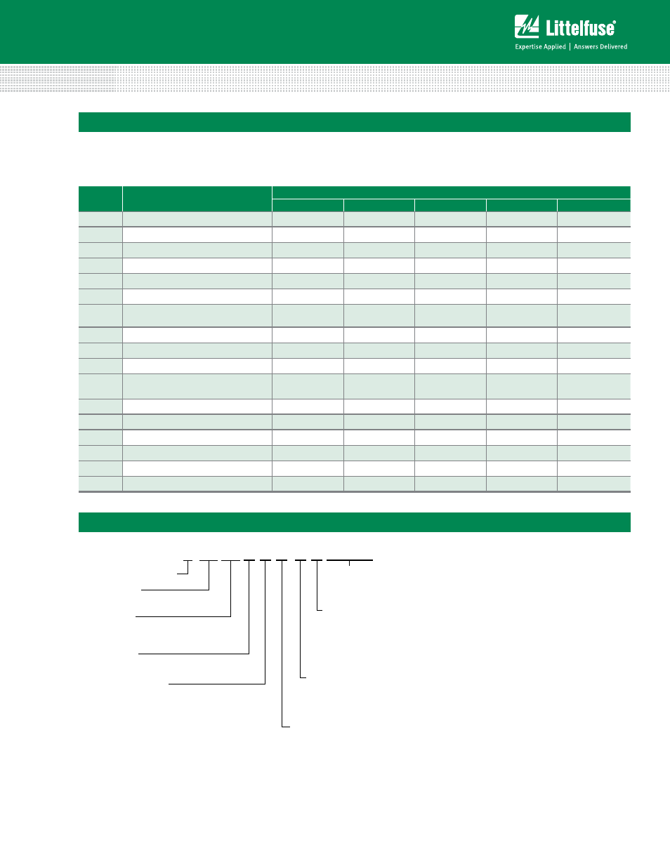
Part Numbering System
Littelfuse Varistor
V 05 E 11
XXXXX
Disc Size
05, 07, 10, 14 or 20 mm
Coating
E: Epoxy
P: Phenolic
VM
(AC)RMS
11V to 40V
P L1 B
Lead-Free and
RoHS Compliant
Other
Non-Standard
Options
Packaging
Blank or B: Bulk Pack
T: Tape and Reel
A: Ammo Pack
5
Lead Spacing Options
Blank: Standard lead spacing
(See Dimensions Table)
5: 5mm+/-1.0mm
7: 7.5mm+/-1.0mm
1: 10mm+/-1.0mm
Lead Formation
Blank or L1: Straight
L2: Crimped
L3: In-Line
L4: Trim/Crimp (Bulk pack only)
SYMBOL
DESCRIPTION
MODEL SIZE
5mm
7mm
10mm
14mm
20mm
P
Pitch of Component
12.7 +/- 1.0
12.7 +/- 1.0
25.4 +/- 1.0
25.4 +/- 1.0
25.4 +/- 1.0
P
0
Feed Hole Pitch
12.7 +/- 0.2
12.7 +/- 0.2
12.7 +/- 0.2
12.7 +/- 0.2
12.7 +/- 0.2
P
1
Feed Hole Center to Pitch
3.85 +/- 0.7
3.85 +/- 0.7
8.85 +/- 0.7
8.85 +/- 0.7
8.85 +/- 0.7
P
2
Hole Center to Component Center
6.35 +/- 1.0
6.35 +/- 1.0
12.7 +/- 0.7
12.7 +/- 0.7
12.7 +/- 0.7
F
Lead to Lead Distance
5.0 +/- 1.0
5.0 +/-1.0
7.5 +/- 1.0
7.5 +/- 1.0
7.5 +/- 1.0
h
Component Alignment
2.0 Max
2.0 Max
2.0 Max
2.0 Max
2.0 Max
W
Tape Width
18.0 +1.0 / -0.5
18.0 +1.0 / -0.5
18.0 +1.0 / -0.5
18.0 +1.0 / -0.5
18.0 +1.0 / -0.5
W
0
Hold Down Tape Width
12.0 +/- 0.3
12.0 +/- 0.3
12.0 +/- 0.3
12.0 +/- 0.3
12.0 +/- 0.3
W
1
Hole Position
9.0 +0.75 / -0.50 9.0 +0.75 / -0.50 9.0 +0.75 / -0.50 9.0 +0.75 / -0.50 9.0 +0.75 / -0.50
W
2
Hold Down Tape Position
0.5 Max
0.5 Max
0.5 Max
0.5 Max
0.5 Max
H
Height from Tape Center to
Component Base
18.0 +2.0 / -0.0
18.0 +2.0 / -0.0
18.0 +2.0 / -0.0
18.0 +2.0 / -0.0
18.0 +2.0 / -0.0
H
0
Seating Plane Height
16.0 +/- 0.5
16.0 +/- 0.5
16.0 +/- 0.5
16.0 +/- 0.5
16.0 +/- 0.5
H
1
Component Height
29.0 Max
32.0 Max
36.0 Max
40.0 Max
46.5 Max
D
0
Feed Hole Diameter
4.0 +/- 0.2
4.0 +/- 0.2
4.0 +/- 0.2
4.0 +/- 0.2
4.0 +/- 0.2
t
Total Tape Thickness
0.7 +/- 0.2
0.7 +/- 0.2
0.7 +/- 0.2
0.7 +/- 0.2
0.7 +/- 0.2
U
Undercrimp Width
8.0 Max
8.0 Max
8.0 Max
8.0 Max
8.0 Max
p
Component Alignment
3° Max
3º
Max
3° Max
3° Max
3° Max
Tape and Reel Specifications (continued)
NOTES:
• Radial devices on tape are supplied with crimped leads, straight leads, or under-crimped leads
• Leads are offset by product dimension e1
• Conforms to ANSI and EIA specifications
• Can be supplied to IEC Publication 286-2