Protection relays & controls, Motor protection–advanced, Features & benefits wiring diagram specifications – Littelfuse MPU-32 (PGR-6200) Series User Manual
Page 2: Motor protection unit
Protection Relays & Controls
© 2013 Littelfuse Protection Relays & Controls
Littelfuse.com/mpu-32
Motor Protection–Advanced
FEATURES
IEEE #
BENEFITS
Overload
49, 51
Extends motor life and prevents insulation failures and fires
Dynamic thermal model
Provides protection through starting, running, and cooling cycles
Communications
Remotely view measured values and event records, reset trips, and access setpoints
Ground fault
50G/N, 51G/N Prevents catastrophic failures and fires
Current unbalance/
Phase loss/Phase reverse
46
Prevents overheating due to unbalanced phases
RTD temperature
38, 49
RTD temperature protection (MPS-RTD module) for high-ambient or loss-of-ventilation protection
Phase loss/Phase reverse (current)
46
Detects unhealthy supply conditions
Overcurrent
50, 51
Prevents catastrophic failures and fires; extends motor life
Jam
Prevents motor damage by detecting mechanical jams or excessive loading
Undercurrent
37
Detects low level or no-load conditions
PTC overtemperature
49
Overtemperature (PTC) protection for high-ambient or loss-of-ventilation detection
Starts per hour
66
Limits the motor starts per hour to prevent overheating
Differential
87
Optional MPS-DIF module for sensitive winding-fault protection
Reduced overcurrent mode
Minimizes arc-flash hazards during maintenance
Metering
View measured and calculated parameters with on-board display
MPU-CIM
Separate current input module to reduce risk of open-CT hazard and for convenient installation
Analog output
Provides means for metering selectable parameters
Data logging
On-board 100-event recorder for data logging
Conformal coating
Internal circuits are conformally coated to protect against corrosion and moisture
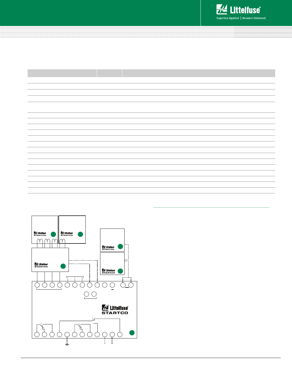
Features & Benefits
Wiring Diagram
Specifications
Protective Functions
(IEEE Device Numbers)
Input Voltage
65-265 Vac, 25 VA; 80-275 Vdc, 25 W
Power-Up Time
800 ms at 120 Vac
Ride-Through Time
100 ms minimum
24-Vdc Source
100 mA maximum
AC Measurements
True RMS and DFT, Peak, 16 samples/cycle, and
positive and negative sequence of fundamental
Frequency
50, 60 Hz or ASD
Output Contacts
Three Form C programmables
Communications
TIA-232 (standard); TIA-485, DeviceNet™, Ethernet (optional)
Analog Output
4-20 mA, programmable
Conformally Coated
Standard feature
Warranty
10 years
Mounting
(Control Unit)
Panel (standard)
Surface (with MPU-32-SMK converter kit)
(Current Input Module) DIN, Surface
Approvals
CSA certified, CE (European Union),
C-Tick (
Australian
)
Overload (49, 51)
Phase reverse (current) (46)
Overcurrent (50, 51)
Jam
Ground fault (50G/N, 51G/N)
PTC overtemperature (49
RTD temperature (38, 49)
Unbalance (current) (46)
Starts per hour (66)
Differential (87)
Phase loss (current) (46)
Undercurrent (37)
......
+
12
11
10
9
8
7
6
5
4
3
2
1
13
14
15
16
17
18
19
26
25
21
22
23
24
27
31
PHASE CURRENT
TRANSFORMERS
GROUND-FAULT
CURRENT
TRANSFORMER
(recommended)
(required)
MPS-RTD
(optional)
INPUT MODULE
MPU-32
MOTOR PROTECTION UNIT
TEMPERATURE INPUT
4-20 mA
ANALOG
OUTPUT
CIM
I/0 MODULE
RELAY 2
RELAY 3
RELAY 1
CONTROL
POWER
DIG IN
CURRENT INPUT MODULE
MPU-CIM
MPS-DIF
DIFFERENTIAL
MODULE
(optional)
A
B
C
D
2
1
MPU-32 SERIES (PGR-6200)
Motor Protection Unit
Rev: 4-A-050213
Based on Manual Rev 4