Littelfuse MPU-32 (PGR-6200) Series User Manual
Protection relays & controls, Motor protection–advanced, Motor protection unit description
Protection Relays & Controls
© 2013 Littelfuse Protection Relays & Controls
Littelfuse.com/mpu-32
Motor Protection–Advanced
MPU-32 SERIES (PGR-6200)
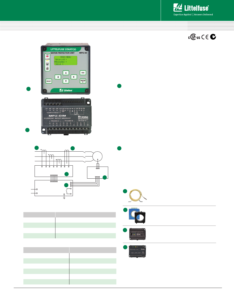
Motor Protection Unit
Description
The MPU-32 Motor Protection Unit is used to provide current-
and temperature-based protection, metering, and data logging
for three-phase low-voltage medium-horsepower induction
motors. This relay is ideal for retrofitting and upgrading obsolete
or aging motor protection using existing CTs. See the PMA
Family of Panel Mount Adapter Kits to replace common
obsolete relays.
Motor Protection Unit
g
Three ac-current inputs
g
Earth-leakage-CT input
g
Programmable digital input
g
24-Vdc source for digital input
g
Programmable 4-20-mA analog output
g
On-board temperature-sensor input,
g
100-
Ω
-Platinum RTD or PTC
g
Three programmable output relays
g
Local RS-232 communications, optional Network Communications
g
PC-interface software (SE-Comm-RIS)
g
4 line x 20 character backlit LCD display
g
Keypad for programming and display selection
g
4 LEDs; 1 user programmable
Current Input Module (MPU-CIM)
The MPU-CIM Current Input Module is the interface between
the MPU-32 relay and the 5-A-secondary, 1-A-secondary, and
sensitive current transformers. The MPU-CIM is ordered
separately from the MPU-32 and can be surface- or DIN-rail
mounted. Wire-clamping terminals are standard but the MPU-CTI
is available for those who require ring-tongue terminals.
ORDERING NUMBER
COMMUNICATION
MPU-32-00-00
TIA-232
MPU-32-01-00
TIA-232 & TIA-485
MPU-32-02-00
TIA-232 & DeviceNet™
MPU-32-04-00
TIA-232 & EtherNet/IP™ & Modbus
®
TCP
NOTE: One of the following is required: MPU-CIM-00-00 Current Input Module, or
MPU-CTI-RT-00 Current Input Module with ring-tonque terminals.
Ordering Information
ACCESSORIES
REQUIREMENT
Phase CTs
Required
MPS-RTD-01-00
Optional
MPS-DIF-01-00
Optional
MPU-32-SMK
Optional
CA-945
Optional
MPU-16A-Y92A-96N
Optional
1
2
1
2
Simplified Circuit Diagram
PHASE CT
PHASE CT
GF CT
PHASE CT
MPU-CIM
MPS-RTD
RTD x 8
L2
L1
MPU-32
M
(Current Input Module)
(Motor Protection Relay)
PHASE CT
PHASE CT
GF CT
PHASE CT
L2
MPS-CTU
L1
M
MPS-RTD
MPS-OPI
RTD x 8
(Control Unit)
(Temperature
Input Module)
(Temperature
Input Module)
(Operator Interface)
D
Phase Current Transformers
Phase CTs are required to detect phase
currents. For upgrade applications, existing
CTs can be used.
Ground-Fault Current Transformer
Optional zero-sequence current transformer detects
ground-fault current. Available with 5-A and 30-A
primary ratings for low-level pickup.
MPS-RTD Temperature Input Module
Optional module provides 8 inputs to connect
Pt100, Ni100, Ni120, and Cu10 RTDs.
MPS-DIF Differential Current Module
Optional motor differential protection,
compatible with core balance and summation
current transformer connections.
B
C
Accessories
A
1
2
B
C
A
Rev: 4-A-050213
Based on Manual Rev 4