Littelfuse T3200 Series User Manual
T3200 insulation monitoring relay
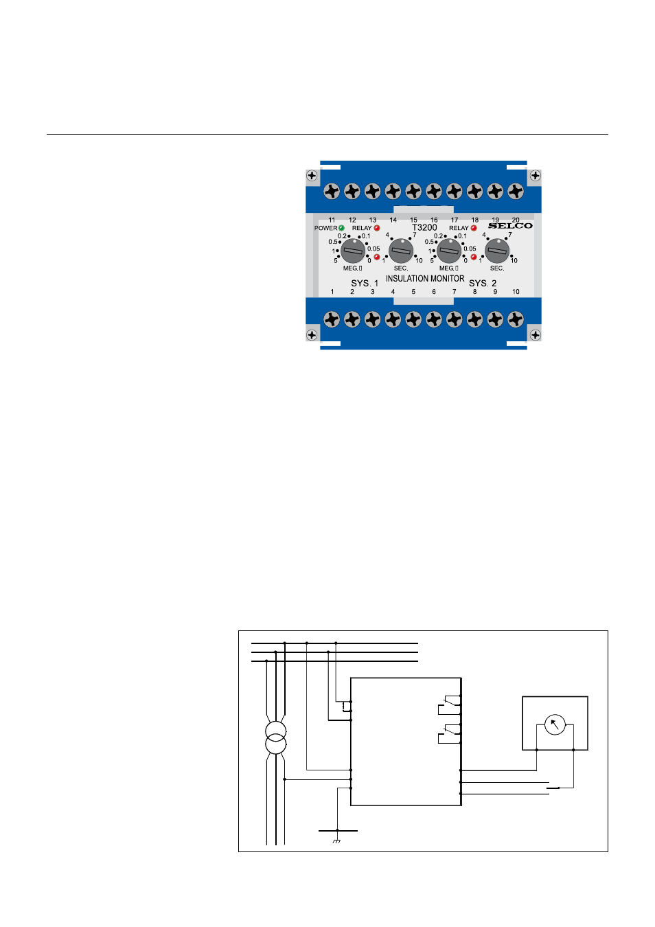
T3200 Insulation Monitoring Relay
Double Insulation Monitoring Relay
• Price competitive due to the
combined functions
• Visual indication of power, pick-up
and relay tripping on both relays
• High precision digital countdown
timer for delayed output
• Cost effective and highly reliable
compact design
• 50 hours burn-in before final test
• Operating temperature range:
-20°C to +70°C
• Certified by major marine
classification societies
• Flame retardant enclosure
• DIN rail or screw mounting
Application
The T3200 Insulation Monitoring Relay
is intended for continuous insulation
monitoring on three-phased insulated
networks on board ships.
The T3200 continuously monitors two
systems, galvanically separated from
each other, e.g. the busbar and the
lighting system, or two busbar systems.
The unit features two output relays for
alarm purposes and two analog outputs
for instrument reading. Instruments are
available from SELCO as standard sized
switchboard instruments.
Function
For each insulation system (I and II) the
electronic measuring circuit will
compare the measured insulation value
to the preset value of the relay. An
insulation drop to a value lower than the
preset value will cause activation of the
corresponding output relay
resulting in alarm signals to be obtained
between terminals 6 and 7 or 9 and 10
(system I or system II respectively).
Consequently, the output relays will be
deactivated when the insulation values
are satisfactory, while insulation values
lower than the preset value will cause
activation of the output relays. This
means that power supply interruptions
will not result in alarm signals as the
output relays normally are deactivated.
The alarm signal can be delayed by
means of a presetting function on the
front of the unit. In this way only
continuous earth faults will cause alarm
signals.
The instrument output has been
adapted for connection of a
megaohmmeter which indicates the
actual insulation level, either by means
of two instruments simultaneously
indicating for both insulation systems (I
and II), or by means of one instrument
which can be connected to the two
instrument outputs via a change-over
switch. See connection diagram.
NOTE: The T3200 operates only on AC
installations. Insulation faults in
connection with thyristor controls and
other semiconductor devices can cause
errors in measurements.
Installation
The measuring circuits for the two
insulation systems I and II are
connected to the network as shown on
the connection diagram.
The supply voltage is connected to
terminals 1-3 or 2-3 according to the
supply source.
Connection Diagram.
SYS. 1
SYS. 2
13
15
11
T3200
3
2
1
10
+
-
20
INS. 2
18
COM.
19
INS. 1
SYS.
2
SYS.
1
7
9
8
6
5
3
L
L
L2
1
E2323