Teccor, Brand thyristors, 65 / 70 amp standard scrs – Littelfuse Sxx70x Series User Manual
Page 4
334
Revised: 09/23/13
©2013 Littelfuse, Inc
Specifications are subject to change without notice.
Teccor
®
brand Thyristors
65 / 70 Amp Standard SCRs
Sxx65x & Sxx70x Series
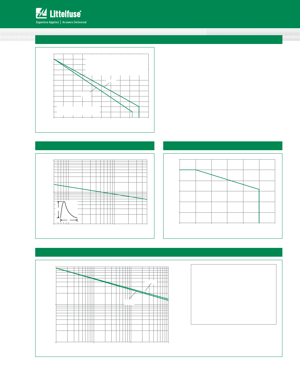
Figure 7: Maximum Allowable Case Temperature vs. Average On-State Current
70
75
80
85
90
95
100
105
110
115
120
125
130
0
5
10
15
20
25
30
35
40
45
50
CURRENT WAVEFORM: Sinusoidal
LOAD: Resistive or Inductive
CONDUCTION ANGLE: 180°
Sxx65K
Sxx65J
Maximum Allo
w
able
Case
Temper
a
tu
re
(T
C
) - °C
Average On-State Current [I
T(AVE)
] - Amps
Sxx70W
The "K" package rating with its narrow leads is
intended for high surge condition use only and not
recommended for >32A (AV) continuous current use
since lead temperature depending on lead length can
exceed PCB solder melting temperature. "J" or "W"
packages are recommended for >32A (AV) continu-
ous current requirements.
10
100
1000
1
10
100
1000
Sxx65K
Sxx65J
Sxx70W
Surge Current Duration -- Full Cycles
P
eak Sur
g
e
(Non-r
epetitiv
e)
On-stat
e Cur
rent (I
TSM
) –
Amps
Figure 10: Surge Peak On-State Current vs. Number of Cycles
SUPPLY FREQUENCY: 60 Hz Sinusoidal
LOAD: Resistive
RMS On-State Current: [I
T(RMS)
]: Maximum Rated
Value at Specified Case Temperature
Notes:
1. Gate control may be lost during and immediately
following surge current interval.
2. Overload may not be repeated until junction
temperature has returned to steady-state
rated value.
Figure 8: Peak Capacitor Discharge Current
Figure 9: Peak Capacitor Discharge Current Derating
100
1000
10000
0.5
1.0
10.0
50.0
P
eak Disc
har
g
e
Cur
rent (I
TM
) -
Amps
Pulse Current Duration (t
w
) - ms
I
TRM
t
W
0.0
0.2
0.4
0.6
0.8
1.0
1.2
0
25
50
75
100
125
150
Nor
maliz
ed P
eak Cur
re
nt
Case Temperature (T
C
) - °C
Note: xx = Voltage