Teccor, Brand thyristors, 65 / 70 amp standard scrs – Littelfuse Sxx70x Series User Manual
Page 3
333
Revised: 09/23/13
©2013 Littelfuse, Inc
Specifications are subject to change without notice.
Teccor
®
brand Thyristors
65 / 70 Amp Standard SCRs
Sxx65x & Sxx70x Series
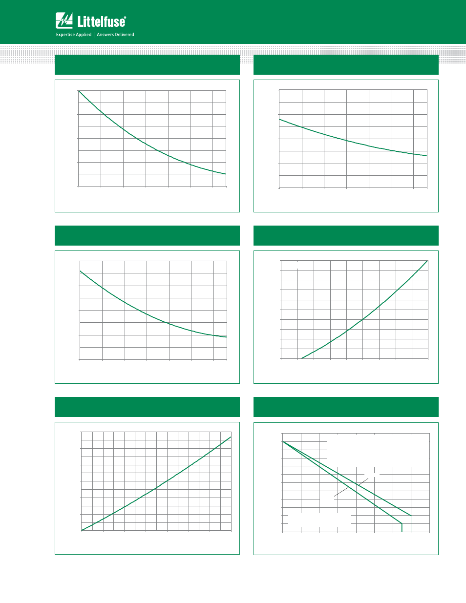
Figure 1: Normalized DC Gate Trigger Current
vs. Junction Temperature
Figure 2: Normalized DC Gate Trigger Voltage
vs. Junction Temperature
0.0
0.5
1.0
1.5
2.0
-40
-15
10
35
60
85
110
Ratio of I
GT
/I
GT
(T
J
= 2
5
°C)
Junction Temperature (T
J
) -- (°C)
125
Figure 5: Power Dissipation (Typical)
vs. RMS On-State Current
Figure 6: Maximum Allowable Case Temperature
vs. RMS On-State Current
Figure 3: Normalized DC Holding Current
vs. Junction Temperature
Figure 4: On-State Current vs. On-State
Voltage (Typical)
0.0
0.5
1.0
1.5
2.0
-40
-15
10
35
60
85
110
Ratio of
V
GT
/V
GT
(T
J
=2
5
°C)
Junction Temperature (T
J
) -- (°C)
125
0.0
0.5
1.0
1.5
2.0
-40
-15
10
35
60
85
110
Ratio of I
H
/I
H
(T
J
=2
5
°C)
Junction Temperature (T
J
) -- (°C)
125
0
20
40
60
80
100
120
140
160
180
200
0.7
0.8
0.9
1.0
1.1
1.2
1.3
1.4
1.5
1.6
Instantaneous On-stat
e Cur
rent (i
T
) –
Amps
Instantaneous On-state Voltage (v
T
) – Volts
T
J
= 25°C
0
10
20
30
40
50
60
0
10
20
30
40
50
60
70
A
v
er
ag
e On-Stat
e P
o
w
er Dissipation
[P
D (A
V)
] - (W at
ts)
RMS On-State Current [I
T(R MS)
] - (Am ps)
70
75
80
85
90
95
100
105
110
115
120
125
130
0
10
20
30
40
50
60
70
80
Maximum Allo
w
able
Case
Temper
at
ur
e
(T
C
)-°C
RMS On-State Current [I
T(RMS)
] - Amps
Sxx70W
Sxx65K
Sxx65J
CURRENT WAVEFORM: Sinusoidal
LOAD: Resistive or Inductive
CONDUCTION ANGLE: 180°
The "K" package rating with its narrow leads is intended
for high surge condition use only and not recom-
mended for >50A rms continuous current use since lead
temperature depending on lead length can exceed PCB
solder melting temperature. "J" or "W" packages are
recommended for >50A rms continuous current require-
ments.
Note: xx = voltage