Littelfuse 600R Series User Manual
Polyfuse, Resettable ptcs, 600r series
107
Revised: July 12, 2010
POLYFUSE
®
Resettable PTCs
© 2010 Littelfuse, Inc
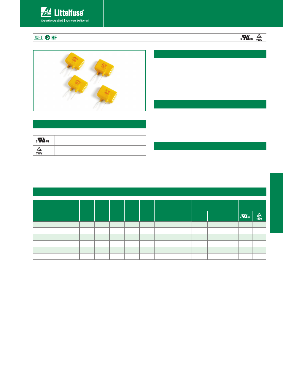
600R Series
Radial Leaded > 600R Series
Specifications are subject to change without notice.
Please refer to www.littelfuse.com/series/600R.html for current information.
60
0R S
eries
t5IF34FSJFTJTEFTJHOFEUPQSPUFDUBHBJOTUQPXFS
fault events typically found in telecom applications. This
series is designed to be used in applications that need to
meet the requirements of GR–1089-CORE and UL60950/
EN60950/IEC60950. These resettable devices also help
to meet the requirements of ITU K.20, K.21 and K.44.
Electrical Characteristics
Part Number
I
hold
(A)
I
trip
(A)
V
max
V
int
/ V
op
I
max
(A)
P
d
typ.
(W)
Maximum Time
To Trip
Resistance
Agency
Approvals
Current
(A)
Time
(Sec.)
R
min
(Ω)
R
typ
(Ω)
R
1max
(Ω)
600R150
0.15
0.30
600/60
3
1.00
1
4.0
6
10
17
X
X
600R150-RA
0.15
0.30
600/60
3
1.00
1
4 . 0
7
10
20
X
X
600R150-RB
0.15
0.30
600/60
3
1.00
1
3.0
9
12
22
X
X
600R160
0.16
0.32
600/60
3
1.00
1
10
4
10
18
X
X
600R160-RA
0.16
0.32
600/60
3
1.00
1
9.5
4
7
16
X
X
600R160-R1
0.16
0.32
600/60
3
1.00
1
9.0
4
8
17
X
X
Description
Features
Applications
to"IPMEDVSSFOU
range, 60VDC operating
voltage
t7"$JOUFSSVQUSBUJOH
t'BTUUJNFoUPUSJQ
t#JOOFEBOETPSUFEOBSSPX
resistance ranges available
t3P)4DPNQMJBOU -FBEo
Free and Halogen-Free*
Secondary overcurrent
protection for:
t$FOUSBM0GmDF
Equipment (CO)
t$VTUPNFS1SFNJTFT
Equipment (CE)
t"MBSNTZTUFNT
t4FU5PQ#PYFT 45#
t7PJDFPWFS*1 70*1
t4VCTDSJCFS-JOF*OUFSGBDF
Circuit (SLIC)
600R Series
Agency Approvals
AGENCY
AGENCY FILE NUMBER
E183209
R50120008
I
hold
= Hold current: maximum current device will pass without tripping in 23°C still air.
I
trip
= Trip current: minimum current at which the device will trip in 23°C still air.
V
int
= Maximum voltage the device can withstand without damage at rated current (I max)
V
op
= The device regular operation voltage
I
max
= Maximum fault current device can withstand without damage at rated voltage (V
max
)
P
d
= Power dissipated from device when in the tripped state at 23°C still air.
R
min
= Minimum resistance of device in initial (un-soldered) state.
R
typ
= Typical resistance of device in initial (un-soldered) state.
R
1max
= Maximum resistance of device at 20°C measured one hour after tripping.
Caution: Operation beyond the specified rating may result in damage and possible arcing
and flame.
*
* Effective February 11, 2010 onward, all 600R PTC products will be manufactured Halogen Free (HF). Existing Non-Halogen Free 600R PTC products may continue to be sold, until
supplies are depleted. This change will have no effect on 600R product specifications or performance.