Transient voltage suppression diodes, Surface mount – 200w > smf series, Physical specifications – Littelfuse SMF Series User Manual
Page 5: Environmental specifications, Soldering parameters, Dimensions, Sod-123f package
Transient Voltage Suppression Diodes
© 2014 Littelfuse, Inc.
Specifications are subject to change without notice.
Revised: 01/20/14
Surface Mount – 200W > SMF Series
Physical Specifications
Case
SOD-123F plastic over glass passivated
junction
Polarity
Color band denotes cathode except bipolar
Terminal
Matte tin-plated leads, solderable per
JESD22-B102
Environmental Specifications
High Temp. Storage
JESD22-A103
HTRB
JESD22-A108
Temperature Cycling
JESD22-A104
MSL
JEDEC-J-STD-020, Level 1
H3TRB
JESD22-A101
RSH
JESD22-B106
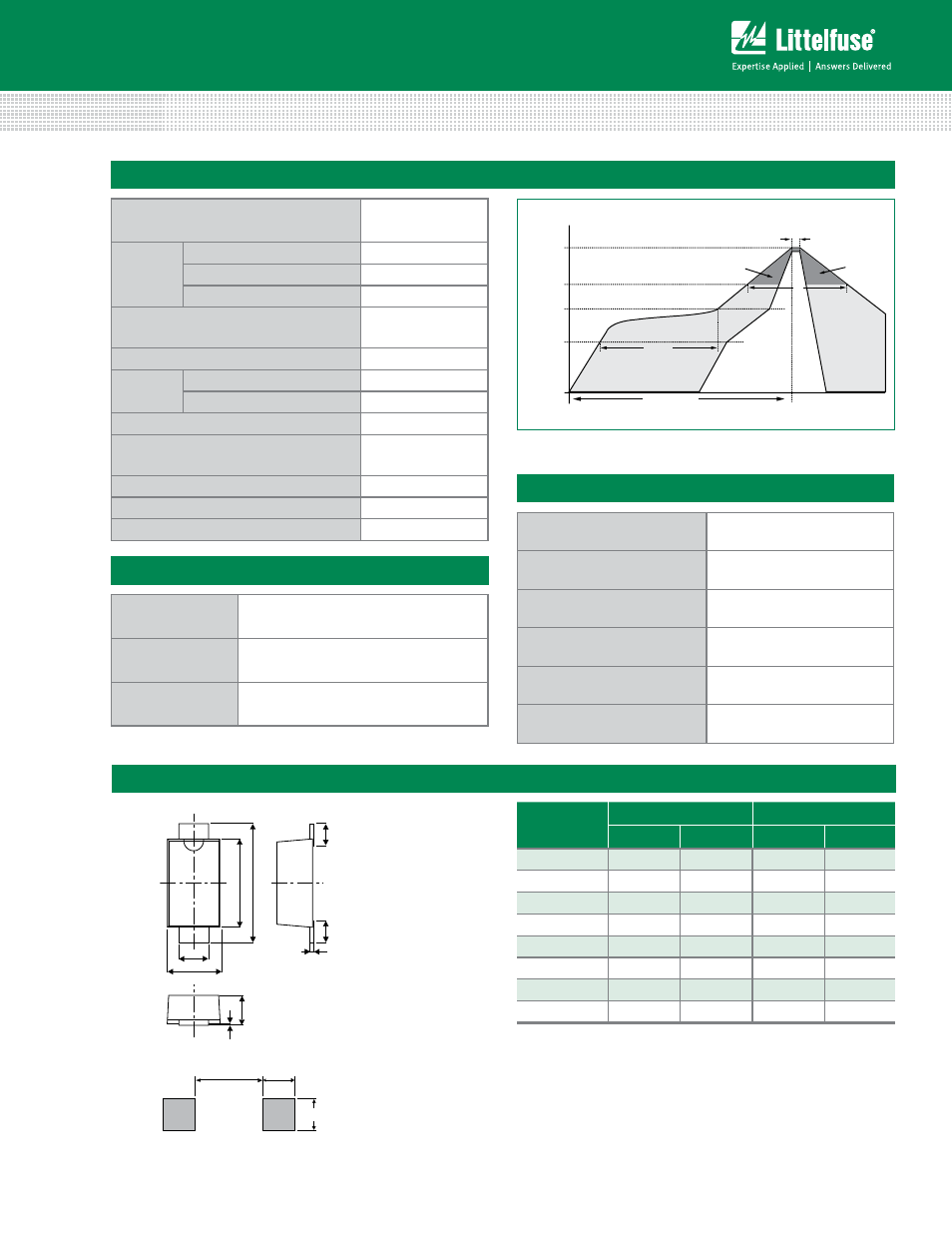
Soldering Parameters
Te
mperature (T
)
Time (t)
T
s(min)
T
s(max)
T
L
T
P
t
s
Preheat
t
L
t
p
Ramp-up
Critical Zone
T
L
to T
P
Ramp-down
t 25˚C to Peak
25˚C
Reflow Condition
Lead–free assembly
Pre Heat
- Temperature Min (T
s(min)
)
150°C
- Temperature Max (T
s(max)
)
200°C
- Time (min to max) (t
s
)
60 – 180 secs
Average ramp up rate (Liquidus Temp
(T
L
) to peak
3°C/second max
T
S(max)
to T
L
- Ramp-up Rate
3°C/second max
Reflow
- Temperature (T
L
) (Liquidus)
217°C
- Time (min to max) (t
s
)
60 – 150 seconds
Peak Temperature (T
P
)
260
+0/-5
°C
Time within 5°C of actual peak
Temperature (t
p
)
20 – 40 seconds
Ramp-down Rate
6°C/second max
Time 25°C to peak Temperature (T
P
)
8 minutes Max.
Do not exceed
260°C
Dimensions
-
SOD-123F Package
Dimensions
Millimeters
Inches
Min
Max
Min
Max
A
2.50
2.90
0.0984
0.1142
B
3.40
3.90
0.1339
0.1535
C
0.70
1.20
0.0275
0.0472
D
1.50
2.00
0.0591
0.0787
E
0.35
0.90
0.0138
0.0354
F
0.05
0.26
0.0020
0.0102
G
0.00
0.10
0.0000
0.0039
H
0.95
1.10
0.0374
0.0433
A
B
C
D
E
E
F
H
G
1.6 (0.062)
1.3 (0.051)
1.4 (0.055)
Mounting Pad Layout