Littelfuse T2800 Series User Manual
T2800 overcurrent or earth fault relay
T2800 Overcurrent or Earth Fault Relay
• Protection of generators against earth
faults or overcurrent
• Visual indication of power, pick-up
and relay tripping
• Wide range of settings for current and
delay, both in two steps.
• High precision digital countdown
timer for delayed output
• Accepts high supply voltage
variations: 60 - 110%
• Cost effective and highly reliable
compact design
• 50 hours burn-in before final test
• Operating temperature range:
-20°C to +70°C
• Flame retardant enclosure
• DIN rail or screw mounting
Application
The T2800 Overcurrent or Earth Fault
Relay has a broad application as an earth
fault or a single phase overcurrent detec-
tion relay. It has a wide setting range for
protection, control and monitoring.
The T2800 is part of the SELCO T-Line
series with modular units for protection,
control and monitoring of generators.
Function
The T2800 detects the magnitude of the
current and, if this exceeds the preset
level (0.02 - 2 x I
N
), the pick-up LED will
indicate and the delay timer will be
started.
After the preset time (0.1 - 10 sec.) has
expired the output relay and the
corresponding LED will be activated,
provided that the current level was
exceeded for the entire delay time.
The T2800 has a normally energized
output relay. The relay is a latching
relay which can be reset or disabled.
Installation
The supply voltage is connected to
terminals 1 and 3 or terminals 2 and 3,
according to the supply source.
The T2800 is connected to the measu-
ring current coming from the current
transducer(s) secondary via terminals
5 and 6. See application diagram.
The latching of the output relays is reset
or disabled by bridging terminals 15
and 16.
The current setting range (0.02 – 0.2 x I
N
)
is multiplied by 10 (0.2 – 2.0 x I
N
) by
bridging terminals 18 and 19.
The delay setting range (0.1 – 1.0 sec.) is
multiplied by 10 (1.0 - 10 sec.) by
bridging terminals 12 and 13.
The current setting can be calculated
according to the following example:
Overcurrent protection of a generator.
Required trip level: 110%
Generator rating: 695A
Current transformer: 800/5A
Setting: 110 x 695/800 = 96% = 0.96 x I
N
Troubleshooting
1) If the relay is not operating please
check that the power LED is on,
ensuring that the supply is present.
2) Measure the supply voltage which
must be compatible with the
information label on top of the
enclosure.
3) Measure the current levels in
erminals 5 and 6 and check that the
current is above setting.
For example:
0.08 x I
N
= 0.4A; 1 x I
N
= 5A
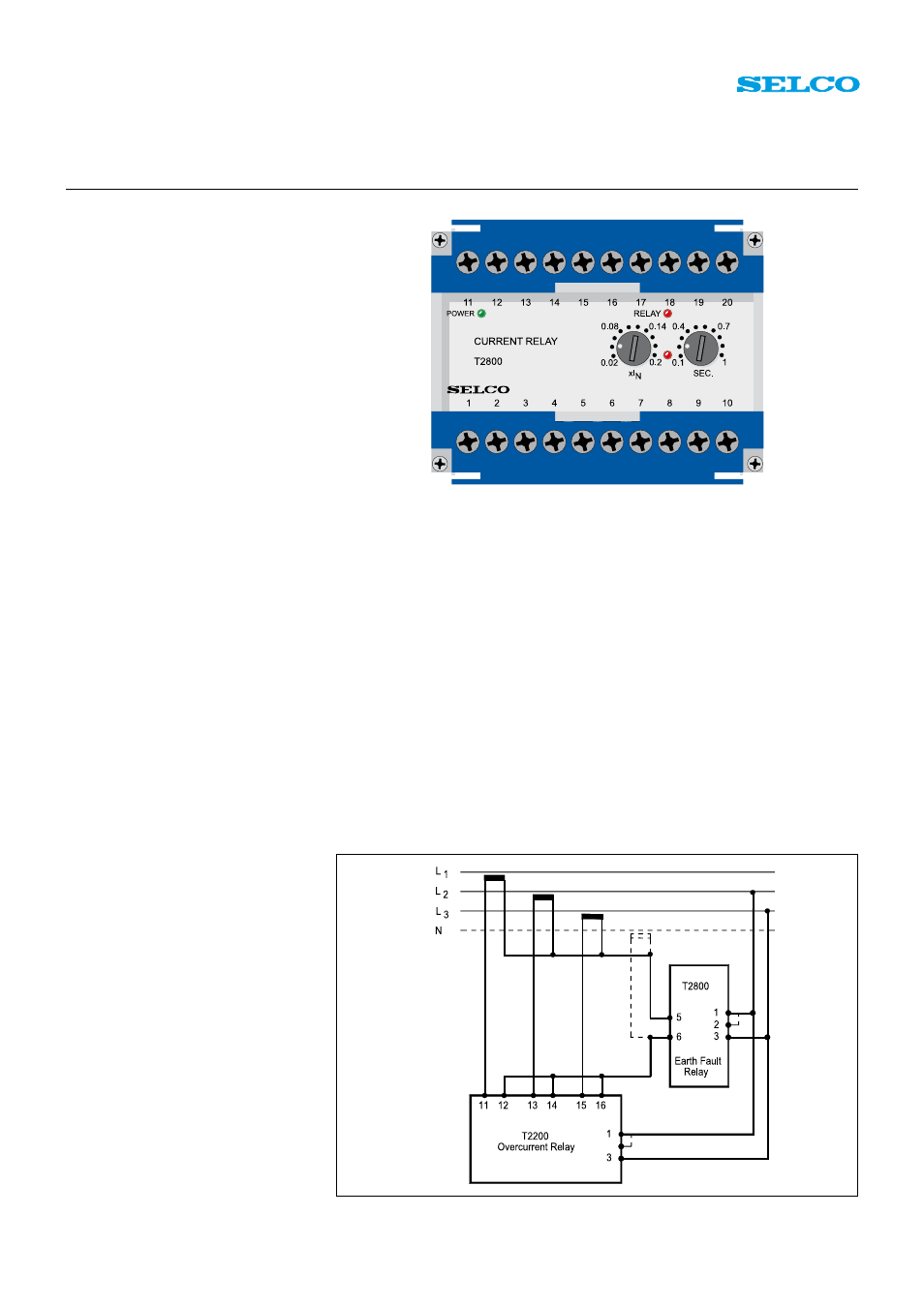
Fig. 1. Application. Earth fault detection and overcurrent detection using same transducers