Protection relays & controls, Wiring diagram, Features & benefits – Littelfuse PGR-8800 Series User Manual
Page 2: Arc-flash relay, Specifications, Accessories, Arc-flash monitoring, Features benefits
Protection Relays & Controls
© 2013 Littelfuse Protection Relays & Controls
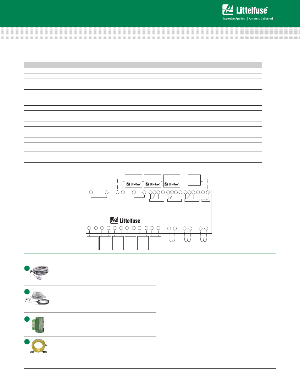
Wiring Diagram
FEATURES
BENEFITS
Arc-Flash trip time <1 ms
Limits arc-flash damage and risk of injury
Multiple sensors (up to 24)
Single module can monitor 6 sensors. Up to 4 PGR-8800 units can be linked into one system
Fail-safe system
Continuous monitoring of optical sensors and inputs ensures protection
Redundant trip circuit
Solid-state backup arc-detection circuit adds a second layer of safety
Adjustable light sensitivity
Allows for operation in bright environments and maximum sensitivity in dark environments
LED indication (on unit and each sensor)
18 LEDs provide at-a glance status for module and I/O state
Current detection
Phase-CT inputs provide overcurrent protection and prevent nuisance trips
Optical detection
Point and fiber-optic sensors provide wide detection area with sensor health trip indication
Digital inputs (6)
Two each: remote trip, inhibit, and reset inputs
Service mode
Allows for system test without tripping
Trip coil contact
Solid-state 24-300 Vdc/24-300 Vac IGBT
Indication contacts
Form C and status outputs
USB interface
Data logging and configuration software uses a USB interface with no drivers or software installation
Built-in sensor
Can be used in single-sensor systems, as a seventh sensor, and for calibration
Universal power supply/Battery backup
100-240 Vac, 14-48 Vdc, or 110-250 Vdc supply accepted. Ability to charge and run off an external, user-supplied
24 Vdc battery.
Data logging
On-board event recorder helps with system diagnostics
Modbus
Remotely view measured values, event records & reset trips
Upstream Tripping
Ability to trip upstream device if the local breaker fails to clear the fault
Features & Benefits
PGR-8800 SERIES (D1000)
Arc-Flash Relay
1
31
36
39
37
45
46 47 48 49 50 51 52 53 54 55 56 57 59 60
38
4
........
5
8
........
9
12
........
13
16
........
17
20
........
21
24
........
.............
.....................
25
26
27
28
29
30
STATUS
STATUS
STATUS
TRIP COIL
TRIPPED
SERVICE
LINK
ONLINE
+
–
CONTROL POWER
and BATTERY
DIGITAL INPUTS
ARC-FLASH RELAY
PGR-8800 SERIES
ARC-FLASH RELAY
PGR-8800
(optional)
DIODE LOGIC
UNIT
PGA-1100
(optional)
ARC-FLASH RELAY
PGR-8800
(optional)
ARC-FLASH RELAY
PGR-8800
(optional)
PHASE CT
(recommended)
PHASE CT
(recommended)
PHASE CT
(recommended)
PGA-LS10
PGA-LS20
PGA-LS25
or
PGA-LS30
OPTICAL
SENSOR
PGA-LS10
PGA-LS20
PGA-LS25
or
PGA-LS30
OPTICAL
SENSOR
PGA-LS10
PGA-LS20
PGA-LS25
or
PGA-LS30
OPTICAL
SENSOR
PGA-LS10
PGA-LS20
PGA-LS25
or
PGA-LS30
OPTICAL
SENSOR
PGA-LS10
PGA-LS20
PGA-LS25
or
PGA-LS30
OPTICAL
SENSOR
PGA-LS10
PGA-LS20
PGA-LS25
or
PGA-LS30
OPTICAL
SENSOR
Specifications
IEEE Device Numbers
Overcurrent (50), Arc Flash (AFD)
Input Voltage
100-240 Vac, 14-48 Vdc, and 110-250 Vdc
Dimensions
H 130 mm (5.2”); W 200 mm (7.9”);
D 54 mm (2.2”)
Optical Trip Settings
9-25 klux, 800 μs-20 s
Current Trip Setting (A)
Programmable
Indication Contact Mode Fail-safe
Trip Coil Voltage
(1)
24-300 Vdc, 24-300 Vac
Trip Coil Contact Mode
Selectable fail-safe or non-fail-safe
Redundant Trip Circuit
Standard feature
Input Monitoring
Standard feature
USB Interface
Standard feature
Trip, Reset,
Service Buttons
Standard feature
Expandable System
Link up to 4 PGR-8800 units
Warranty
5 years
Mounting
DIN (with D0050 adapter clips), Surface
PGA-LS10 (A1000) Point Sensor
Line-of-sight light sensor detects an arc as small as 3 kA
within a 2-m half-sphere. Sensor health and trip indication.
Dimensions: See PGR-8800 Manual
PGA-LS20 (A2000)/PGA-LS25 (A2000.0020)/PGA-
LS30(A2000.0030) Fiber-Optic Sensor
360° light sensor for tricky installations with many shadows
or to run along bus bars. Sensor health and trip indication.
Dimensions: See PGR-8800 Manual
PGA-1100 (D1100) Diode Logic Unit
This module allows multiple PGR-8800 relays to trip the
same breaker, for example an upstream or a tie-breaker.
Dimensions: H 80mm (3.15”) W 20mm(.79”) D 70mm(2.76”)
Current Transformers
Eliminate nuisance arc-flash trips and use for
overcurrent protection.
Accessories
A
B
D
C
Littelfuse reserves the right to make product changes, without notice. Material in this document is as accurate as known at the time of publication. Visit Littelfuse.com for the most up-to-date information.
Littelfuse.com/ArcFlash
NOTE (1) - Contact Littelfuse for trip coil voltages higher than 300 Vdc/Vac.
Rev: 4-F-012214
Based on Manual Rev 3-A-112913
Arc-Flash Monitoring