Littelfuse PGR-8800 Series User Manual
Protection relays & controls, Description, Optical sensors
Protection Relays & Controls
© 2013 Littelfuse Protection Relays & Controls
Littelfuse.com/ArcFlash
Rev: 4-F-012214
Based on Manual Rev 3-A-112913
Description
The PGR-8800 is a microprocessor-based relay that limits
arc-fault damage by detecting the light from an arc flash and
rapidly tripping. Phase-current-transformer inputs are provided
for current-constrained arc-flash protection and, when so
equipped, a programmable definite-time overcurrent function
can be enabled. An optical sensor on the PGR-8800 and
adjustable trip level reduce the chance of nuisance tripping
by setting a threshold for ambient light. Sensors, inputs, and
connections are monitored to ensure fail-safe operation. A
secondary solid-state trip circuit provides a redundant trip path.
A USB port is used for configuration and access to event logs
and graphs.
Optical Sensors
The PGR-8800 accepts both PGA-LS10 and PGA-LS20/PGA-
LS25/PGA-LS30 optical sensors, designed to collect light over
a wide angle and with high sensitivity. For fast fault location,
front-panel and sensor LED’s indicate sensor health and which
sensor detected an arc fault.
Sensor Placement
The PGR-8800 Arc-Flash Relay and sensors are easily
installed in retrofit projects and new switchgear with little or
no re-configuration. Even elaborate systems with multiple
power sources take minutes to configure using the relay’s
built-in USB interface software.
Generally, it is recommended to mount 1 or 2 sensors per
cubicle to cover all horizontal and vertical bus bars, breaker
compartments, drawers, and anywhere that there is potential
for an arc-fault. Threading a fiber-optic sensor through
the cabinets and in areas where point-sensor coverage is
uncertain results in complete coverage and an added level
of redundancy. Even if policy is to only work on de-energized
systems, all maintenance areas should be monitored to
prevent potential damage and additional cost. At least one
sensor should have visibility of an arc fault if a person blocks
the other sensor(s).
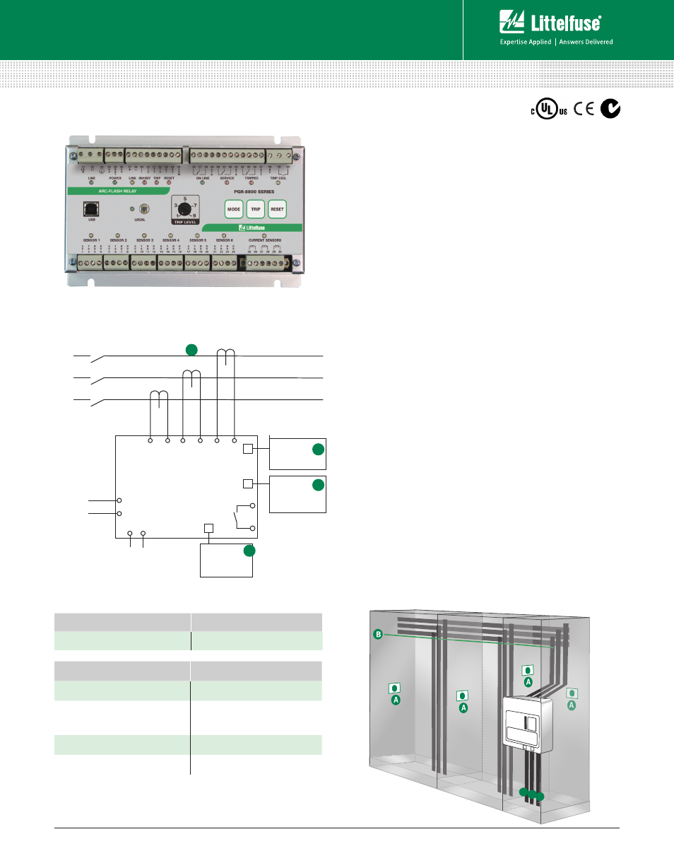
Simplified Circuit Diagram
PGA-LS10
(Point Sensor)
PGA-LS20/
PGA-LS25/
PGA-LS30
(Fiber-Optic Sensor)
PGA-1100
(Diode Logic Unit)
(Optional)
24 Vdc Battery
Backup
(Optional)
(Recommended)
(Arc-Flash Protection Relay)
PGR-8800
Trip
5-A-SECONDARY PHASE CT’s
L2
L1
A
B
C
A
B
Ordering Information
PGR-8800 SERIES (D1000)
Arc-Flash Relay
C
D
ORDERING NUMBER
COMMUNICATIONS
PGR-8800-00 (UL, CE, C-tick)
Multi-unit linking,
Modbus
®
RTU
ACCESSORIES
REQUIREMENT
PGA-LS10 (A1000)
Required*
PGA-LS20 (A2000)/
PGA-LS25 (A2000.0020)
PGA-LS30 (A2000.0030)
Required*
PGA-1100 (D1100)
Optional
Current Transformer
Recommended
*At least one sensor is required. However, the exact number of sensors for proper coverage
depends on the application.
D D D
Local
Circuit Breaker
For detailed wiring diagram, see adjacent page.
Arc-Flash Monitoring