Littelfuse SP721 Lead-Free_Green Series User Manual
Tvs diode arrays, General purpose esd protection - sp721 series, Diodes)
© 2013 Littelfuse, Inc.
Specifications are subject to change without notice.
Revised: 04/24/13
TVS Diode Arrays
(SPA
®
Diodes)
General Purpose ESD Protection - SP721 Series
Description
Features
• ESD Interface Capability for HBM Standards
- MIL STD 3015.7 ................................................. 15kV
- IEC 61000-4-2, Direct Discharge,
- Single Input .......................................... 4kV (Level 2)
- Two Inputs in Parallel ............................ 8kV (Level 4)
- IEC 61000-4-2, Air Discharge ...............15kV (Level 4)
• High Peak Current Capability
- IEC 61000-4-5 (8/20µs) ....................................... ±3A
- Single Pulse, 100µs Pulse Width ........................ ±2A
- Single Pulse, 4µs Pulse Width ............................ ±5A
• Designed to Provide Over-Voltage Protection
- Single-Ended Voltage Range to ........................ +30V
- Differential Voltage Range to ............................ ±15V
• Fast Switching .............................................2ns Rise Time
• Low Input Leakages ............................1nA at 25ºC Typical
• Low Input Capacitance .....................................3pF Typical
• An Array of 6 SCR/Diode Pairs
• Operating Temperature Range....................-40ºC to 105ºC
Applications
The SP721 is an array of SCR/Diode bipolar structures for
ESD and over-voltage protection to sensitive input circuits.
The SP721 has 2 protection SCR/Diode device structures
per input. There are a total of 6 available inputs that can be
used to protect up to 6 external signal or bus lines. Over-
voltage protection is from the IN (Pins 1 - 3 and Pins 5 - 7)
to V+ or V-.
The SCR structures are designed for fast triggering at a
threshold of one +V
BE
diode threshold above V+ (Pin 8) or
a -V
BE
diode threshold below V- (Pin 4). From an IN input,
a clamp to V+ is activated if a transient pulse causes the
input to be increased to a voltage level greater than one
V
BE
above V+. A similar clamp to V- is activated if a negative
pulse, one V
BE
less than V-, is applied to an IN input.
Standard ESD Human Body Model (HBM) Capability is:
• Microprocessor/Logic
Input Protection
• Data Bus Protection
• Analog Device Input
Protection
• Voltage Clamp
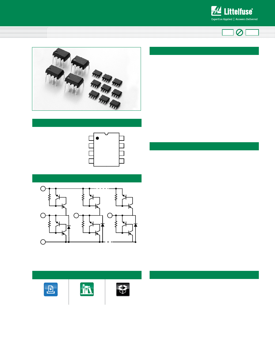
Pinout
Functional Block Diagram
4
V+
V-
IN
3, 5-7
IN
IN
1
8
2
SP721 (PDIP, SOIC)
TOP VIEW
IN
IN
IN
V-
1
2
3
4
8
7
6
5
V+
IN
IN
IN
RoHS
Pb
GREEN
SP721 Series 3pF 4kV Diode Array
Additional Information