Sidactor, Protection thyristors, Baseband protection (voice-ds1) – Littelfuse T10A Series DO-15 User Manual
Page 2
SIDACtor
®
Protection Thyristors
177
Revised: February 22, 2011
© 2011 Littelfuse, Inc.
Specifications are subject to change without notice.
Please refer to www.littelfuse.com for current information.
Baseband Protection (Voice-DS1)
Package
Symbol
Parameter
Value
Unit
DO-15
T
J
Operating Junction Temperature Range
UP
°C
T
S
Storage Temperature Range
UP
°C
R
0JA
Thermal Resistance: Junction to Ambient
120
°C/W
Thermal Considerations
Surge Ratings
Series
I
PP
I
TSM
50/60 Hz
di/dt
8x20
1
1.2x50
2
5x310
1
10x700
2
10x1000
1
10x1000
2
A min
A min
A min
A min
A/μs max
A
100
37.5
50
20
100
Electrical Characteristics (continued)
Part Number
Marking
V
DRM
@l
DRM
=5μA
V
S
@100V/μs
I
H
I
S
I
T
V
T
@I
T
=2.2 Amp
Capacitance
@ 1MHz, 2V Bias
V Min
V Max
mA Min mA Max A Max
V Max
pF Typ
T10A220Bxx
T10A220B
200
275
120
800
2.2
4
30
T10A220Exx
T10A220E
200
275
180
800
2.2
4
30
T10A240xx
T10A240
216
330
150
800
2.2
4
30
T10A270xx
T10A270
245
370
150
800
2.2
4
30
T10A270Bxx
T10A270B
245
370
120
800
2.2
4
30
T10A270Exx
T10A270E
245
370
180
800
2.2
4
30
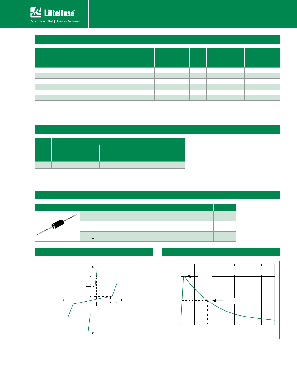
I
H
I
T
I
S
I
DRM
V
DRM
V
T
+V
-V
+I
-I
V
S
50
100
0
t
r
t
d
0
Peak
Value
Half Value
t – Time (μs)
I
PP
– P
eak Pulse Current – %I
PP
t
r
= rise time to peak value
t
d
= decay time to half value
Waveform = t
r
x t
d
V-I Characteristics
t
r
x t
d
Pulse Waveform
Notes:
1 Current waveform in μs
2 Voltage waveform in μs
Notes:
t"CTPMVUFNBYJNVNSBUJOHTNFBTVSFEBU5
A
= 25ºC (unless otherwise noted).
t%FWJDFTBSFCJEJSFDUJPOBM VOMFTTPUIFSXJTFOPUFE
tXX1BSU/VNCFS4VGmTiRPw 3FFM1BDLPSBlank (Bulk Pack)
- Peak pulse current rating (I
PP
) is repetitive and guaranteed for the life of the product.
- I
PP
SBUJOHTBQQMJDBCMFPWFSUFNQFSBUVSFSBOHFPG$UP$
- The device must initially be in thermal equilibrium with -40°C < T
J
<¡$