Generator control, Basic and advanced wiring diagram specifications, Flexgen technical data – Littelfuse C6200 Flexgen Series User Manual
Page 2: Features & benefits, Phase true rms measurement, Frequency control, Automatic synchronization, Active load sharing, Voltage control/voltage matching, Reactive load sharing
Generator Control
© 2013 Littelfuse Protection Relays & Controls
www.littelfuse.com/c6200
Basic and Advanced
Wiring Diagram
Specifications
Auxiliary Supply
10 Vdc to 36 Vdc (24 Vdc-58%/+50%)
Generator Voltage
63 V-690 V
Generator Rated Frequency 50 Hz/60 Hz
C/T Secondary Current
5 A
Consumption
7 W
Burden C/T Input
0.4 VA at I
N
Ambient Temp Range
–20°C to +70°C
Vibration
IEC 60068-2-6
Humidity
IEC 60068-2-30
EMC
IEC 61000-4-3:2006, IEC 61000-4-6:2004,
IEC 61000-4-5:2005, IACS E10:2006 Test No.15,
CISPR 16-1:1999, CISPR 16-2:2002
Relay Contacts
230 Vac/2 A & 30 Vdc/2 A
External Communication
MODBUS RTU
Enclosure IP20
Weight
1,5 Kg
Dimensions
H 182 mm (7.2”); W 282 mm (11.1”);
D 50 mm (2.0”)
FlexGen Technical Data
FeAtureS
BASiC
AdVAnCed
3-phase true RMS measurement
•
•
Frequency control
•
•
Automatic synchronization
•
•
Active load sharing
•
•
Voltage control/Voltage matching
•
Reactive load sharing
•
Reverse power protection
•
•
Excitation loss protection
•
RoCoF protection (df/dt)
•
Vector shift protection
•
Overcurrent (I >) and
Overload protection (P>)
•
Short-circuit protection (I >>)
•
Overvoltage (U >)
•
•
Undervoltage (U <)
•
•
Overfrequency (F >)
•
•
Underfrequency (F <)
•
•
Dead bus monitoring /Black-out limiter
•
•
External circuit-breaker trip
•
Engine error trip
•
Preferential load trip (PM)
•
Load depending start/stop (PM)
•
Large consumer control (PM)
•
Dynamic grid-parallel operation control
•
Analog I/O
•
MODBUS RTU (RS485 interface)
•
•
FeAtureS
BeneFitS
3-phase true RMS
measurement
Reliable measurement, high noise immunity
Analog outputs for speed
and voltage control
Fits most electronic governors and ECUs
PWM outputs for speed
and voltage control
Compatible with e.g. CAT and Woodward
Pulse outputs for speed
and voltage control
Compatible with conventional governors,
motorized potentiometers and some ECUs
10 programmable
Inputs and outputs
Flexible configuration for a wide range of
applications such as marine PMS, on site
power or grid parallel applications
Type-approved by marine
classification societies
Approved for marine power management
Features & Benefits
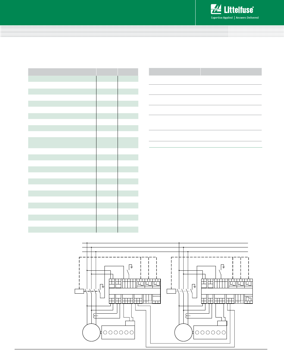
S
1
DG1
L1
L2
L3
C/B
Busbar
Voltage
C/B Close
1
2
L1 L2
29 31
+
-
Aux.
Supply
40 41 42 43 44
Re
se
t A
larm
U
nlo
ad
M
an
ua
l
C/B
45 46 47 48 49 50 51 52 53
Prot. Trip
UnloadTrip
5
6
L1 L2
Gen.
Voltage
13 14
S2/
L3
S1/
L3
Gen.
Current
32 33
ref pwm
al
An og Out 1
Speed Control
34 35
mA V/
DC
26 27
kW gnd
ParallelLines
28
VAr
Alarm
65 66 67
Prg
. O
ut.
3
Prg
. O
ut.
2
Prg
. O
ut.
1
54 55 56
G ND
G overnor
G ND
S
1
DG2
C/B
Busbar
Voltage
C/B Close
1
2
L1 L2
29 31
+
-
Aux.
Supply
40 41 42 43 44
Re
se
t A
larm
U
nlo
ad
C/B
B
loc
k
C/B
45 46 47 48 49 50 51 52 53
Prot. Trip
Unload Trip
5
6
L1 L2
Gen.
Voltage
13 14
S2/
L3
S1/
L3
Gen.
Current
32 33
ref pwm
Analog Out 1
Speed Control
34 35
mA V/
DC
26 27
kW gnd
ParallelLines
28
VAr
Alarm
65
66 67
Prg
.O
ut.
3
Prg
.O
ut.
2
Prg
.O
ut.
1
54 55 56
Fre
q. C
trl.
D
isa
ble
G ND
G overnor
G ND
Fre
q. C
trl.
D
isa
ble
FLEX GEN GENERATOR CONTROL
C6200
FLEX GEN GENERATOR CONTROL
C6200
Rev: 4-A-050313