Ac700-cua firmware upgrade module – Littelfuse AC700 Series User Manual
Page 6
Rev. 0
Page 3
AC700-CUA Firmware Upgrade Module
2. I
NSTALLATION
N
OTE:
Before performing service on product, remove supply and control voltage.
2.1 F
IRMWARE
U
PGRADE
M
ODULE
I
NSTALLATION
x
Remove system and control voltage from the device.
x
Remove the access panel from device to be upgraded (See Fig.3).
x
Slide module into opening, such that the rails on the circuit board slot align
with the sides of the firmware upgrade module. See Fig 3.
x
Apply pressure to ensure proper connection.
x
Connect either a TIA 232 or mini-USB communications cable between the
module and a computer.
x
Follow the SE-Flash Help instructions for the product to be upgraded, and
apply system power.
2.2 C
OMMUNICATIONS
M
ODULE
I
NSTALLATION
x
Remove system and control voltage from the device.
x
Remove the access panel from device to be upgraded (See Fig.3).
x
Slide module into opening, such that the rails on the circuit board slot align
with the sides of the communication module. See Fig 4 and 5.
x
Apply pressure to ensure proper connection while aligning clips to circuit
board.
x
Tighten the installation screws using a Torx screwdriver, size 8 (T8).
x
Connect the communications cable as required by the network interface.
x
See the manual for the upgraded device for instructions on how to enable the
communications module, and definitions of the LED indications.
x
Apply system power.
Rev. 0
Page 4
AC700-CUA Firmware Upgrade Module
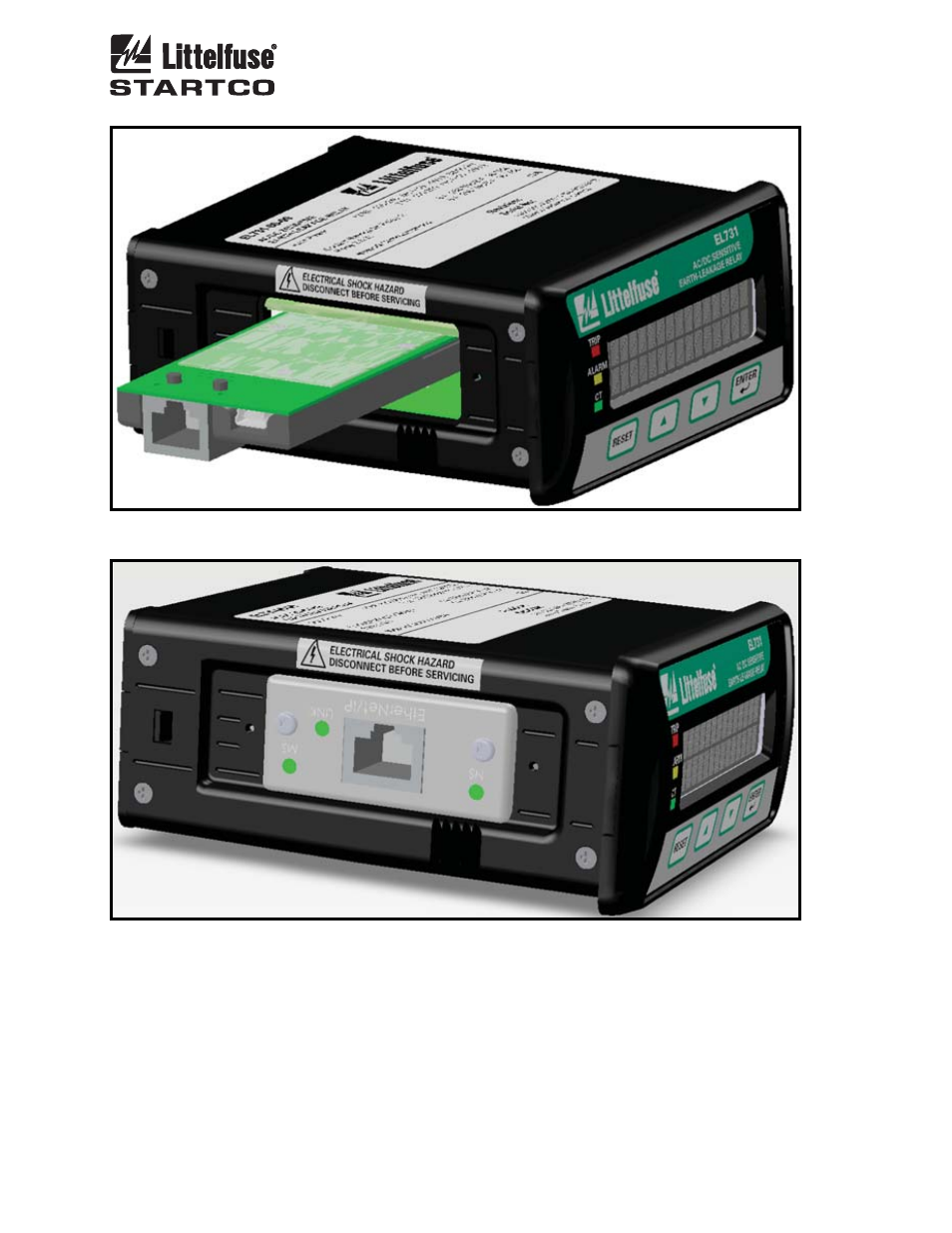
FIGURE 3 Firmware Upgrade Module (AC700-CUA-00) in an EL731.
FIGURE 4. Ethernet/IP Communications (AC700-CUA-03) Module installed in an
EL731.