Pgr-6150 series, Protection relays & controls, Specifications – Littelfuse PGR-6150 Series User Manual
Page 2: Dynamic thermal modeling, Wiring diagram, Motor protection system
Protection Relays & Controls
© 2013 Littelfuse Protection Relays & Controls
Littelfuse.com/pgr-6150
Features & Benefits
Motor Protection–Standard (PGR 6000 Family)
FeaTuReS
ieee #
beneFiTS
No CTs required
49, 51
No current transformers are required for currents < 25 A
Adjustable trip settings
Adjustable overload trip class setting from 5 to 45 to match motor characteristics
Digital input
Programmable digital input
Output contacts
Two programmable Form C output contacts for operation of separate annunciation and trip circuits
Overload
49, 51
Extends motor life and prevents insulation failures and fires
Overcurrent/Jam
50, 51
Detects catastrophic failures and fires; extends motor life
Undercurrent
37
Detects low level or no-load conditions
Unbalance (current)
46
Prevents overheating due to unbalanced phases
Phase loss/Phase sequence
46
Detects unhealthy supply conditions
PTC overtemperature
49
Detect high ambient or blocked ventilation and single phasing; prevents shaft/pump damage
Dynamic thermal model
Provides protection through starting, running, overload, and cooling cycles
Communications
RS-485 communications to remotely display metered values
Specifications
Protective Functions
(IEEE Device Numbers)
Input Voltage
110-230 Vac/Vdc; 24/48 Vdc, 5 W
AC Measurements
RMS, 16 samples/cycle
Frequency
50, 60 Hz
Dimensions
(Control Unit)
H 83 mm (3.3”); W 78 mm (3.1”); D 99 mm (3.9”)
(Operator Interface)
H 56 mm (2.2”); W 106 mm (4.2”); D 22.8 mm (0.9”)
Output Contacts
Two Form C
Communications
RS-485 with Modbus
®
RTU
Approvals
UL Listed (E353735), CE (European Union)
Warranty
5 years
Mounting
DIN (Control Unit); Panel (Operator Interface)
Overload (49, 51)
Phase sequence (46)
Overcurrent (50, 51)
Jam
Ground fault (50G/N, 51G/N)
Undercurrent (37)
PTC overtemperature (49)
Failure to accelerate
RTD temperature (49)
Unbalance (current) (46)
Starts per hour (66)
Phase loss (current) (46)
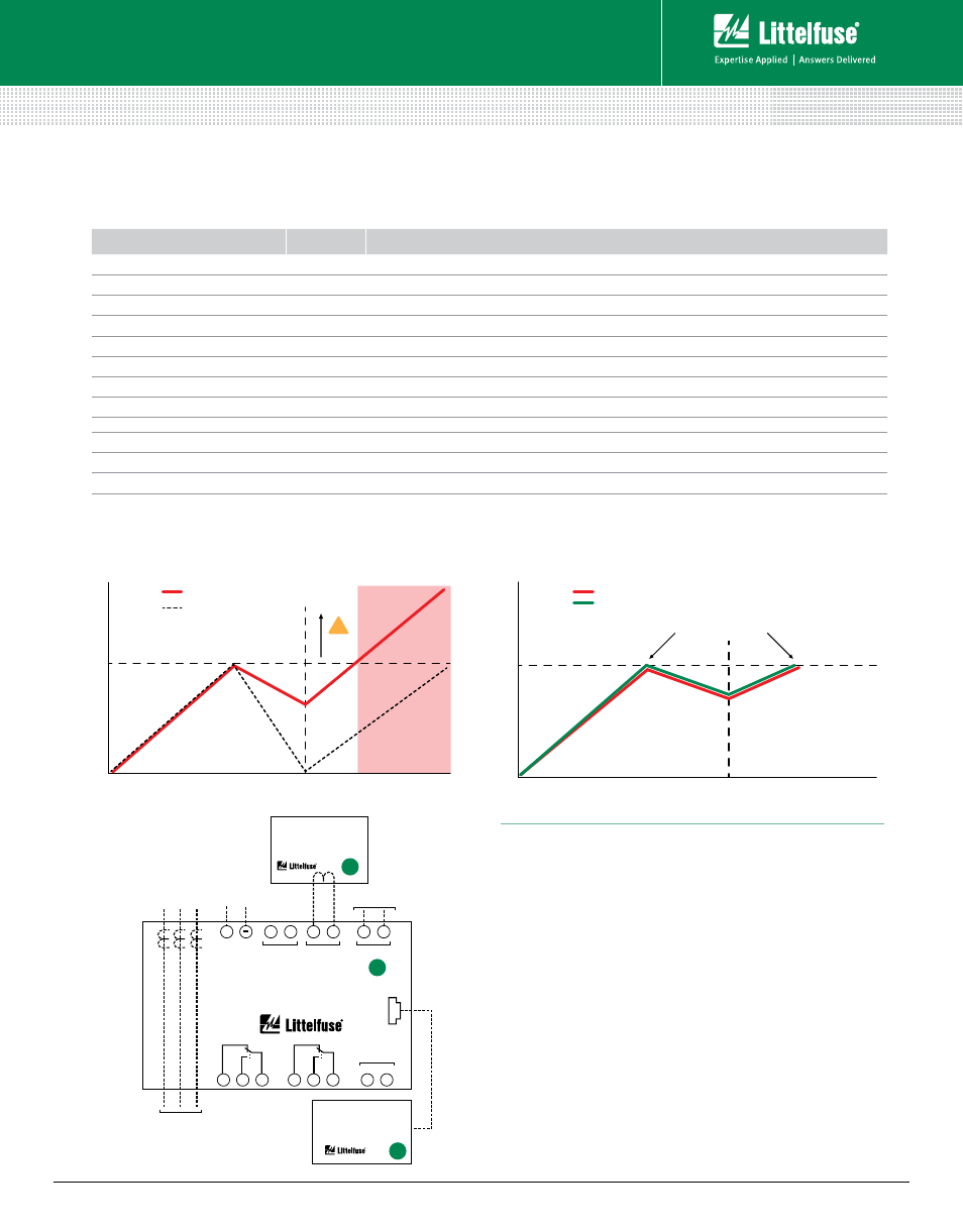
Dynamic Thermal Modeling
Maximum Operating Temperature
Temper
at
ur
e
Time
With PGR-6150 the
temperature is not exceeded,
no damage to motor
Motor
PGR-6150
Maximum Operating Temperature
For every 10°C over
insulation temperature
rating the motor loses
50% of its life span.
Temper
at
ur
e
Time
Motor
Traditional
Overload
!
Da
m
ag
e i
s c
au
se
d,
de
cre
as
es
m
ot
or
lif
e
Tra
dit
ion
al
Ov
erl
oa
d r
es
ets
be
for
e m
oto
r h
as
co
ole
d d
ow
n
With Thermal Memory
Without Thermal Memory
MOTOR PROTECTION SYSTEM
PGR-6150 SERIES
TEMPERATURE
INPUT
DIGITAL
INPUTS
3
4
CT
GF
5
6
PTC
7
8
12
14
11
22
24
21
K1
K2
RS-485
+
–
10
9
CONTROL
POWER
L2/N
L1
GROUND-FAULT
CURRENT TRANSFORMER
PGC-6000 SERIES
FEEDER TO MOTOR
3 PHASE CTs
BUILT INTO RELAY.
EXTERNAL CTs
REQUIRED FOR
FLA >25 A.
OPERATOR INTERFACE
PGR-6150-OPI
+
(optional)
(optional)
Wiring Diagram
B
A
1
PGR-6150 SeRieS
Motor Protection System
Rev: 4-A-050213
Based on Manual Rev 1