Fps series, Protection relays & controls, Feeder protection–advanced – Littelfuse FPS Series User Manual
Page 2: Wiring diagram, Specifications, Features & benefits, Feeder protection system
Protection Relays & Controls
© 2013 Littelfuse Protection Relays & Controls
Littelfuse.com/fps
Feeder Protection–Advanced
PHASE
VOLTAGES
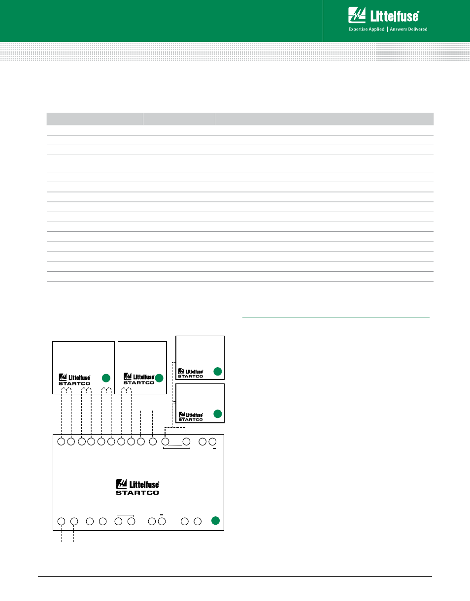
FPS-CTU
CONTROL UNIT
RELAY
OUTPUTS
I/0 MODULE
DIGITAL
INPUTS
4-20 mA
ANALOG
INPUT
+
ANALOG
OUTPUT
4-20 mA
+
39
40
53
52
43
51
......
5
16
......
1
2
60
56
20
17
......
33
22
CONTROL
POWER
RS-485
35
37
......
30 29
27
26
23
22
PHASE CURRENT
TRANFORMERS
GROUND-FAULT
CURRENT
TRANSFORMER
OPERATOR INTERFACE
FPS-OPI
(recommended)
(required)
(recommended)
RTD MODULE
MPS-RTD
(optional)
Wiring Diagram
A
B
C
1
2
Specifications
Protective Functions
(IEEE Device Numbers)
Input Voltage
65-265 Vac, 25 VA; 80-275 Vdc, 25 W
Power-Up Time
800 ms at 120 Vac
Ride-Through Time
100 ms minimum
24-Vdc Source
100 mA maximum
AC Measurements
True RMS and DFT, Peak, 16 samples/cycle, and
positive and negative sequence of fundamental
Frequency
50 or 60 Hz
Inputs
Phase current, Earth-leakage current, Phase voltage,
7 digital, 1 analog
Output Contacts
5 contacts — See Product Manual
Approvals
CSA certified, C-Tick (
Australian
)
Communications
Allen-Bradley
®
DFI and Modbus
®
RTU (Standard);
DeviceNet™, Profibus
®
, Ethernet (Optional)
Conformal Coating
Standard feature
Warranty
10 years
Mounting:
Control Unit Surface
Operator Interface
Panel, Control-Unit mounted
Overload (49, 51)
Phase reverse (current) (46)
Overfrequency (81)
Overcurrent (50, 51)
Underfrequency (81)
Ground fault (50G/N, 51G/N)
Unbalance (voltage) (47)
RTD temperature (38, 49)
Unbalance (current) (46)
Phase loss (voltage) (47)
Overvoltage (59)
Phase loss (current) (46)
Undervoltage (27)
Phase reverse (voltage) (47)
Power factor (55)
Features & Benefits
FEAtuRES
IEEE #
bEnEFItS
Overload
49, 51
Long-time overcurrent provides thermal protection for feeder or load
Inverse-time overcurrent
50, 51
Coordination using IEEE and IEC Curves
Definite-time overcurrent
50, 51
Instantaneous overcurrent to detect catastrophic failure
Current unbalance/
Phase loss/Phase reverse
46
Detects an open or high-impedance phase
Ground fault
50G/N, 51G/N
Inverse and definite time. Early insulation-failure detection.
RTD temperature
38, 49
Optional protection (MPS-RTD module) for load-temperature monitoring
Overvoltage
59
Limits stress to insulation
Undervoltage
27
Detects a damaging brown-out condition
Voltage unbalance
47
Detects unhealthy supply voltage
Two setting groups
Minimizes Arc-Flash hazards during maintenance
Breaker control
Allows local and remote operation; reduces component count
Metering
Displays the measured and calculated parameters
Data logging
On-board 64-event recorder helps with system diagnosis
Communications
Remotely view measured values, event records, & reset trips
Conformal coating
Internal circuits are conformally coated to protect against corrosion and moisture
FPS SERIES
Feeder Protection System
Rev: 4-A-050213
Based on Manual Rev 0