Varistor products, Device ratings and specifications – Littelfuse MLE Varistor Series User Manual
Page 2
© 2013 Littelfuse, Inc.
30
Revised: December 16, 2013
Varistor Products
MLE Varistor Series
Surface Mount Multilayer Varistors (MLVs) > MLE Series
Specifications are subject to change without notice.
Please refer to www.littelfuse.com/series/MLE.html for current information.
Device Ratings and Specifications
Part Number
Max Continuous
Working Voltage
-55ºC to 125ºC
Performance Specifications (25ºC)
Nominal
Voltage
Maximum Clamping
Voltage at Specified
Current (8/20
µs)
Maximum ESD Clamp
Voltage
(Note 2)
Typical
Capacitance
at 1MHz
(Note 1)
V
M(DC)
V
NOM
at
1mA DC
V
C
8kV Contact
(Note 3)
15kV Air
(Note 4)
(V)
MIN (V)
MAX (V)
(V)
(V)
Clamp (V)
(pF)
V18MLE0402N
18
22
28
50 at 1A
<125
<110
<55
V18MLE0603N
18
22
28
50 at 1A
<75
<110
<125
V18MLE0603LN
18
22
28
50 at 1A
<100
<140
<100
V18MLE0805N
18
22
28
50 at 1A
<70
<75
<500
V18MLE0805LN
18
22
28
50 at 1A
<75
<135
<100
V18MLE1206N
18
22
28
50 at 1A
<65
<65
<1700
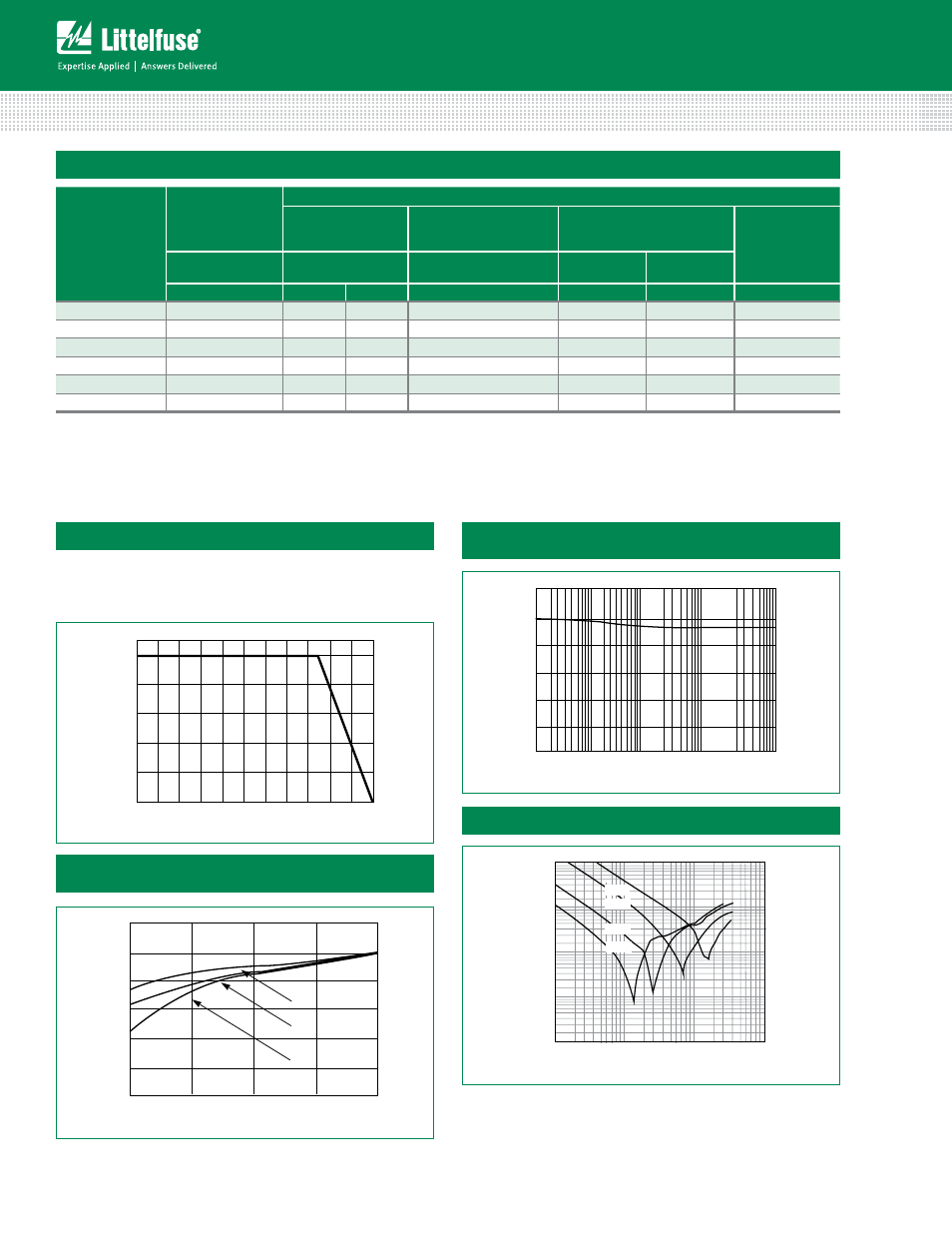
For applications exceeding 125ºC ambient temperature, the
peak surge current and energy ratings must be reduced as
shown below.
Peak Current and Energy Derating Curve
Nominal Voltage Stability to Multiple ESD Impulses
(8kV Contact Discharges per IEC 61000-4-2)
FIGURE 4. IMPEDANCE (Z) vs FREQUENCY
TYPICAL CHARACTERISTIC
0.1
FREQUENCY (MHz)
IMPED
ANCE (Z)
10
100
1000
10000
1
10
100
0.01
-0402
-0603
-0805
-1206
Standby Current at Normalized Varistor Voltage and
Temperature
Impedance (Z) vs Frequency Typical Characteristic
NOTES:
1. For applications of 18V
DC
or less. Higher voltages available, contact your Littelfuse Sales Representative.
2. Tested with IEC-61000-4-2 Human Body Model (HBM) discharge test circuit.
3. Direct discharge to device terminals (IEC preferred test method).
4. Corona discharge through air (represents actual ESD event).
5. Capacitance may be customized, contact your Littelfuse Sales Representative.
6. Leakage current ratings are at 18 V
DC
and 25µA maximum.
FIGURE 2. NOMINAL VOLTAGE STABILITY TO MULTIPLE
ESD IMPULSES (8KV CONTACT DISCHARGES
PER IEC 61000-4-2)
25
0
1
CURRENT (A)
NOMINAL
VO
LTA
GE
AT
1mADC
10
100
1000
10000
5
10
15
20
30
1.2
0.0
0.0001
25
0.001
0.01
0.1
1
CURRENT (mA)
NORMALIZED
VARIS
TOR
VO
LTA
GE (V)
FIGURE 3. STANDBY CURRENT AT NORMALIZED VARISTOR
VOLTAGE AND TEMPERATURE
1.0
0.8
0.6
0.4
0.2
85
125
O
O
O
100
80
60
40
20
0
-55
50
60
70
80
90 100 110 120 130 140 150
PERCENT OF
RA
TED
VALUE
AMBIENT TEMPERATURE (
o
C)
FIGURE 1. PEAK CURRENT AND ENERGY DERATING CURVE
Figure 1
Figure 2
Figure 3
Figure 4