Gas discharge tube (gdt) products, Device dimensions – Littelfuse SL1024A_B Series User Manual
Page 4
©2010 Littelfuse, Inc.
Gas Discharge Tube (GDT) Products
21
Revised: June 28, 2010
Specifications are subject to change without notice.
Please refer to www.littelfuse.com for current information.
Customer should verify actual device performance in their specific applications.
SL1021A/B, SL1024A/B and PMT8 Series
SL1021A/B, SL1024A/B and PMT8 Series
8.1
[0.319]
10.10
[0.398]
9.9
[0.354]
9.9
[0.354]
10.10
[0.398]
4.4± 0.3
[0.173± 0.12]
4.4± 0.3
[0.173± 0.12]
15
[0.590]
16.8
[0.661]
4.4
[0.173]
1.0 DIA.
[0.039]
12.4 ± 1
[0.488 ± 0.039]
11.8
[0.464]
11.8
[0.464]
8.1.
[0.319]
9.9
[0.354]
16.8
[0.661]
11.8
[0.464]
6.35 ± 0.5
[0.25 ± 0.25]
15
[0.590]
1.0 DIA.
[0.039]
8.1 DIA. MAX.
[0.319]
10.10
[0.398]
14.7
[0.579]
6.35 ± 0.5
[0.25 ± 0.25]
9.0
[0.354]
0.3mm
Minimum
Gap
0.3mm
Minimum
Gap
0.3mm
Minimum
Gap
Mounting Area
9.0
[0.354]
Mounting Area
9.0
[0.354]
Mounting Area
9.9
[0.354]
10.10
[0.398]
5.5± 0.3
[0.216± 0.12]
5.5± 0.3
[0.216± 0.12]
15
[0.590]
16.8
[0.661]
4.4
[0.173]
1.0 DIA.
[0.039]
12.4 ± 1
[0.488 ± 0.039]
11.8
[0.464]
8.1.
[0.319]
0.3mm
Minimum
Gap
9.0
[0.354]
Mounting Area
10.10
[0.398]
22
[0.866]
1.0 DIA..
[0.039]
50 ± 3
[1.968 ± 0.118 ]
8.1 DIA. MAX.
[0.319]
11.8
[0.464]
23.8
[0.937]
9.0
[0.354]
Mounting Area
0.3mm
Minimum
Gap
Type 01 / C
Type 60
Type 06 / Y
Type 14 / X
Type 04 / R
Type 05 / P
PROFILE VIEW
SOLDERING PAD LAYOUT
SIDE VIEW
TOP VIEW
7.7 ± 0.3
[0.303 ± 0.019]
10.0 ± 0.3
[0.394 ± 0.019]
Ø7.0 ± 0.1
[0.275 ± 0.004]
8.3 +0.3/-0.0
[0.327
+0.019/-0.00]
8.0 +0.3/-0.1
[0.315
+0.019/-0.004]
8.5 ± 0.0
[0.335 ± 0.000]
2.2 ± 0.0
[0.087 ± 0.000]
6.0 ± 0.0
[0.236 ± 0.000]
10.75 ± 0.0
[0.423 ± 0.000]
1.2 ± 0.0
[0.047 ± 0.000]
1.2 ± 0.0
[0.047 ± 0.000]
Overall Product Space
DO NOT ENCROACH
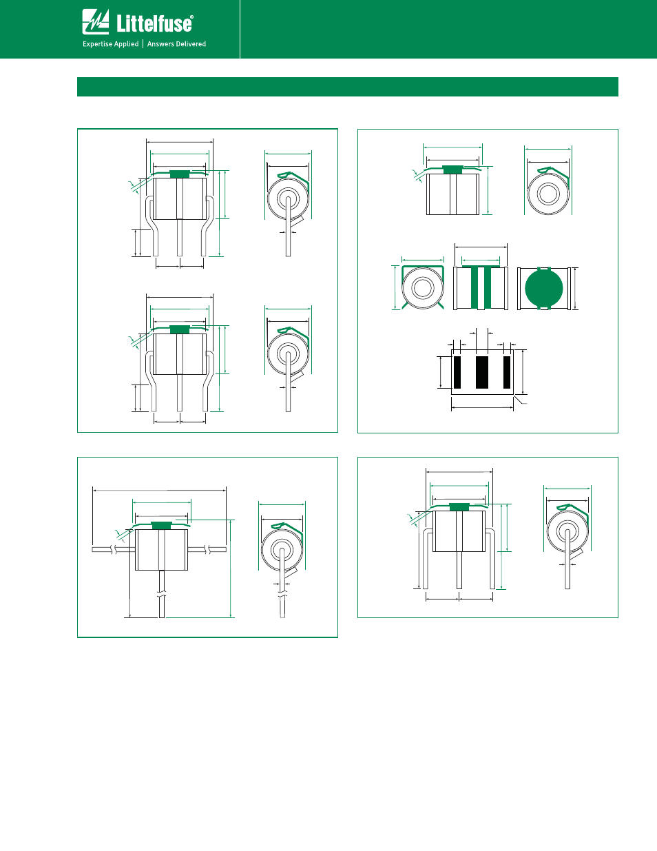
Device Dimensions
NOTE: Failsafe option dimensions shown in
green.
Shaped Radial Leaded Devices:
Surface Mount Devices:
Straight Radial Leaded Devices:
Straight "T" Leaded Devices: