Varistor products, 34s series, Lead configurations tmov – Littelfuse TMOV 34S Varistor Series User Manual
Page 6: 34s "e" 2-lead varistor tmov, 34s "m" 3-lead varistor
© 2013 Littelfuse, Inc.
228
Revised: December 16, 2013
Varistor Products
TMOV
®
34S Varistor Series
Industrial High Energy Thermally Protected Varistors > TMOV
®
34S Series
Specifications are subject to change without notice.
Please refer to www.littelfuse.com/series/tmov34s.html for current information.
R
LED
Line Fuse
TMOV34S “M”
Varistor
Neutral
Line
Figure 1. Application example 1
R
Line Fuse
Neutral
Figure 2. Application example 2
AC OPTOCOUPLER
TO STATUS
ANNUNCIATOR
LIGHT/ALARM
Line Fuse
Neutral
Figure 3. Application example 3
Fault LED
(Normallyoff)
"Load Powered"
neon lamp
Load Switch Relay
(loss of protection)
R
To Protected Circuit
To Protected Circuit
To Protected Circuit
Line
Line
TMOV34S “M”
Varistor
TMOV34S “M”
Varistor
1
2
3
3
2
1
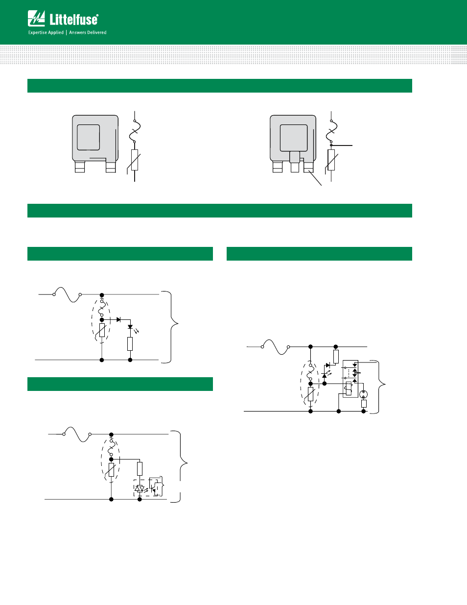
Thermal
Fuse
Element
MOV
Thermal
Fuse
Element
MOV
Monitor Lead
Monitor Lead
Lead Configurations
TMOV
®
34S "E" 2-Lead Varistor
TMOV
®
34S Varistor Application Examples
The application examples below show how the monitor lead on the TMOV
®
34S
can be used to indicate that the thermal
element has been opened. This signifies that the circuit is no longer protected from transients by the MOV.
Application Example 1
In this case, the LED is normally on, and is off when the
thermal element opens.
Application Example 2
This circuit utilizes an optocoupler to provide
galvanic isolations between the TMOV
®
34S
varistor and the indicating or alarm circuitry.
Application Example 3
This circuit illustrates the use of the monitoring lead of
the TMOV
®
34S varistor to ensure that equipment is only
operated when overvoltage protection present. In normal
operation the load switch relay solenoid is powered via the
monitor lead of the TMOV
®
34S varistor. In the event of the
thermal element being activated, the relay will de-activate,
cutting power to the protected circuit and the fault LED will
illuminate.
R
LED
Line Fuse
TMOV34S “M”
Varistor
Neutral
Line
Figure 1. Application example 1
R
Line Fuse
Neutral
Figure 2. Application example 2
AC OPTOCOUPLER
TO STATUS
ANNUNCIATOR
LIGHT/ALARM
Line Fuse
Neutral
Figure 3. Application example 3
Fault LED
(Normallyoff)
"Load Powered"
neon lamp
Load Switch Relay
(loss of protection)
R
To Protected Circuit
To Protected Circuit
To Protected Circuit
Line
Line
TMOV34S “M”
Varistor
TMOV34S “M”
Varistor
R
LED
Line Fuse
TMOV34S “M”
Varistor
Neutral
Line
Figure 1. Application example 1
R
Line Fuse
Neutral
Figure 2. Application example 2
AC OPTOCOUPLER
TO STATUS
ANNUNCIATOR
LIGHT/ALARM
Line Fuse
Neutral
Figure 3. Application example 3
Fault LED
(Normallyoff)
"Load Powered"
neon lamp
Load Switch Relay
(loss of protection)
R
To Protected Circuit
To Protected Circuit
To Protected Circuit
Line
Line
TMOV34S “M”
Varistor
TMOV34S “M”
Varistor
Please note: Indicator circuits are provided as a
guideline only. Verification of actual indicator circuitry
is the responsibility of the end user. Component
values selected must be appropriate for the specific
AC line voltage service and application.
TMOV
®
34S "M" 3-Lead Varistor
Note: MOVs are non-polarized passive elements