Varistor products, Surface mount varistors > ch series – Littelfuse CH Varistor Series User Manual
Page 6
© 2013 Littelfuse, Inc.
74
Revised: May 8, 2013
Varistor Products
CH Varistor Series
Surface Mount Varistors > CH Series
Specifications are subject to change without notice.
Please refer to www.littelfuse.com/series/CH.html for current information.
Notes :
• Conforms to EIA-481-1, Revision A
• Can be supplied to IEC P ublication 286-3
Standard Packaging*
CH Series varistors are always shipped in tape and reel.
The standard 13-inch reel utilized contains 4000 pieces.
Note also that the CH Series receives no branding on the
chip itself.
*NOTE: It is recommended that parts be kept in the sealed
bag provided and that parts be used as soon as possible
when removed from bags.
Special Packaging
Option 1
7-inch reels containing 1000 pieces are
available. To order 7-inch reels add a 'T' suffix to
the part number; e.g., V47CH8T.
Option 2
For small quantities (less than 100 pieces) the
units are shipped bulk pack. To order, add a 'S'
suffix to the part number; e.g., V47CH8S.
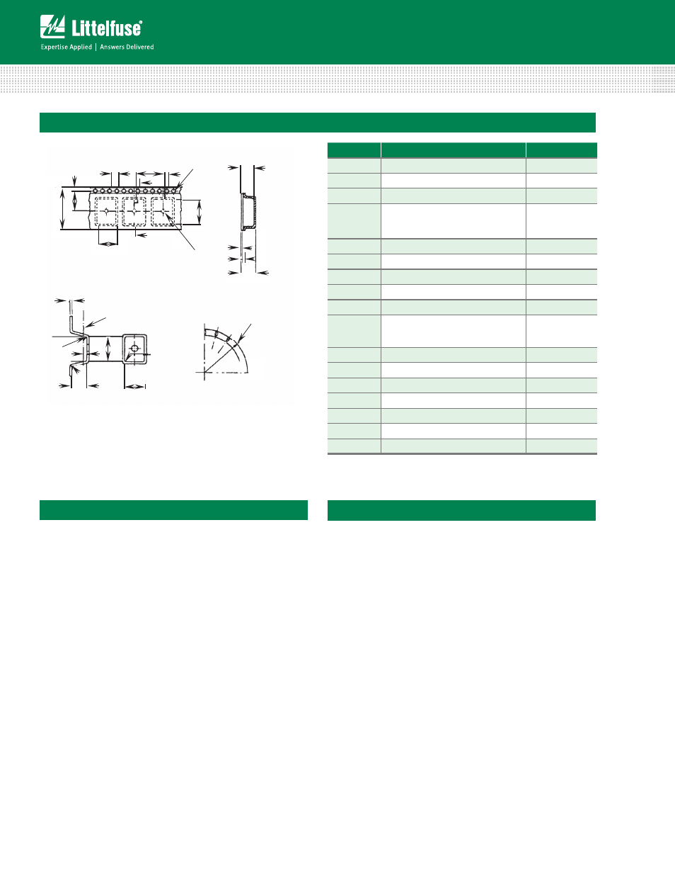
Symbol
Parameter
Size (mm)
B
0
Cavity Length
8.5 -/+ 0.1
A
0
Cavity Width
5.5 -/+ 0.1
K
0
Cavity Depth
2.0 Min.
H
0
Ref. Plane for A0 and B0
+ 0.10
0.3
- 0.05
R
1
, R
2
, R
3
Tape Cavity Radii
0.5 Max.
T
Carrier Tape Thickness
1.0 Max.
T
1
Cover Tape Thickness
0.1 Max.
E
Sprocket Hole from Edge
1.75 -/+ 0.1
P
0
Sprocket Hole Pitch
4.0 -/+ 0.1
D
Sprocket Hole Diameter
+ 0.1
1.5
- 0.0
P
2
Hole Centre to Component Centre
2.0 -/+ 0.15
R
4
Min. Bending Radius
30.5 Min.
D
1
Ejection Hole Diameter
1.5 Min.
K
Overall Thickness
3.0 Min.
P
Pitch Of Component
8.0 -/+ 0.1
F
Sprocket Hole to Ejection Hole
7.5 -/+ 0.1
W
Carrier Tape Width
16.0 -/+ 0.3
B
0
D
P
2
P
P
0
A
0
D
1
E
F
W
CROSS SECTION
(REF. PLANE FOR A
0
& B
0
)
T
R
1
R
2
K
0
A
0
R
3
B
0
H
0
K
0
SECTION
THRU
CAVITY
T
1
T
K
MINIMUM
BENDING
RADIUS
R
4
CAVITY DETAILS
REELED RADIUS DETAILS
PLAN VIEW OF STRIP
Tape and Reel Specifications