Littelfuse T4400 Series User Manual
Page 3
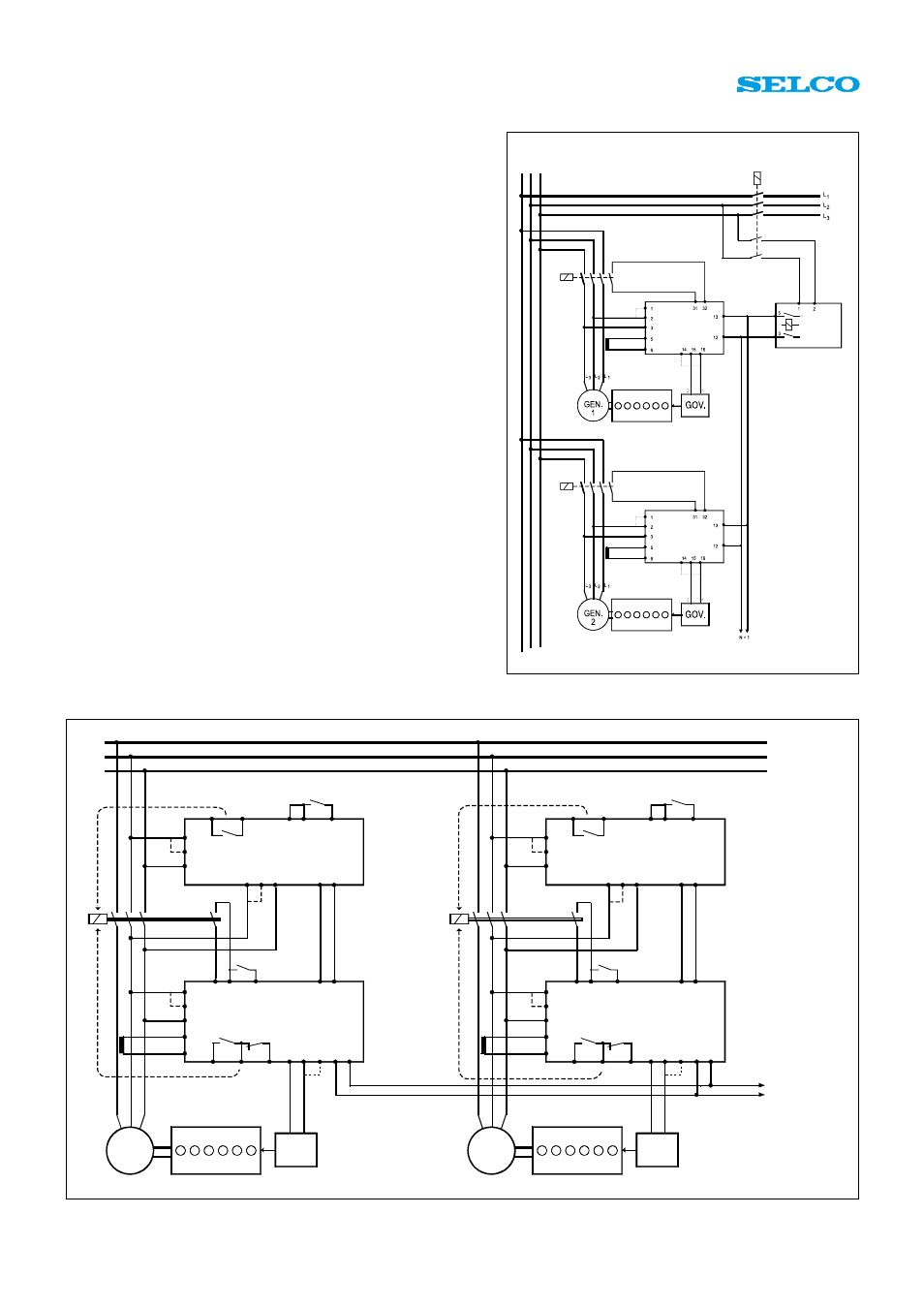
Fig. 3. Application Diagram. Synchronization and load sharing with the T4000, T4400 and a speed controller with -5V to +5V DC input.
2. Output from terminals 15 (REF.) and
16 (+) must be connected to the speed
controller input. Terminal 16 is going
positive for increased load. If a
negative voltage for increased load is
needed, then terminal 14 (-) should
be used rather than terminal 16 (+).
3. The parallel lines connected to
terminals 12 (COM.) and 13 (+)
between load sharers must not be
interchanged.
If the load balance is incorrect
If there is a balance point, but the load
balance is incorrect, the following
should be checked:
1. Load deviation shall be set to 0 for
same size of generators and same
type of current transducers (CTs).
2. The frequency of the generators
before paralleling should be the same.
3. The output adjustment must have
the same setting on all load sharers.
4. If the deviation from other
generators is approximately two
times, it is likely that the current on
terminals 5 and 6 is measured in one
of the phases supplying the T4400.
The current must be measured in the
phase that is not supplying the unit
(see the application diagram in fig. 1).
L1
L2
L3
1
2
3
9 10 13 12 15
5 6 7 21 22-27
31 32 7 12 9
23 24 25 15 16 14 12 13
1
2
3
9 10 13 12 15
5 6 7 21 22-27
1
2
3
6
5
31 32 7 12 9
23 24 25 15 16 14 12 13
1
2
3
6
5
L1 L2 L3
L1 L2 L3
0
+
_
0
+
_
UNLOAD
UNLOAD
SYNCHRONIZER T4000
SYNCHRONIZER T4000
LOAD SHARER T4400
LOAD SHARER T4400
GEN 1
GOV.
D/G 1
GEN 2
GOV.
D/G 2
SYNCHRONIZE
SYNCHRONIZE
TO NEXT
T4400
13
12
UNLO
AD - AND REV
.PO
WER
TRI
P
UNLO
AD - AND REV
.PO
WER
TRI
P
CLOSE
CLOSE
BUS
MAINS-SWITCH
POWER
REFERENCE
B9300-XX-14
LOAD SHARER
T4400
LOAD SHARER
T4400
BUS
GRID
Fig. 2. Application Diagram: B9300 with T4400.
Check the voltage on
terminal 11 (TEST
OUT) to be +6V DC
for nominal current
input (I
N
=1A or I
N
=5A)
and power factor = 1.0.
A current
measurement in a
wrong phase will give
+3V DC.
Example:
If the current in
terminals 5 and 6 is
2.0A, the nominal
current I
N
is 5A, and
the power factor is 0.8,
then the voltage for
correct connection is:
2
6 x _ x 0.8 = +1.9V.
5
If the load is fluctuating
up and down
If there is a correct
balance point, but the
load is fluctuating up
and down, the
STABILITY should be
turned clockwise in order
to obtain stability, but not
more than necessary.