Transient voltage suppression diodes, Surface mount – 600w > sma6j series, I-v curve characteristics – Littelfuse SMA6J Series User Manual
Page 2: Figure 2 - peak pulse power rating curve, Electrical characteristics
Transient Voltage Suppression Diodes
© 2014 Littelfuse, Inc.
Specifications are subject to change without notice.
Revised: 01/20/14
Surface Mount – 600W > SMA6J series
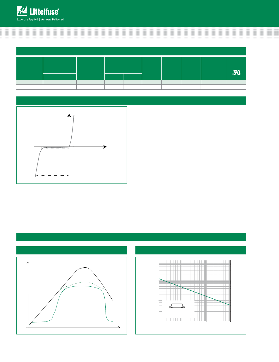
I-V Curve Characteristics
Voltage Transients
Time
Voltage Across TVS
Current Through TVS
Voltage or Current
Figure 1 - TVS Transients Clamping Waveform
Ratings and Characteristic Curves
(T
A
=25°C unless otherwise noted)
Figure 2 - Peak Pulse Power Rating Curve
Vc V
BR
V
R
I
R
I
T
I
pp
V
Uni-directional
V
F
P
PPM
Peak Pulse Power Dissipation -- Max power dissipation
V
R
Stand-off Voltage -- Maximum voltage that can be applied to the TVS without operation
V
BR
Breakdown Voltage -- Maximum voltage that flows though the TVS at a specified test current (I
T
)
V
C
Clamping Voltage -- Peak voltage measured across the suppressor at a specified Ippm (peak impulse current)
I
R
Reverse Leakage Current -- Current measured at V
R
V
F
Forward Voltage Drop for Uni-directional
continues on next page.
Electrical Characteristics
(T
A
=25°C unless otherwise noted)
Part
Number
(Uni)
Marking
Reverse Stand
off Voltage V
R
(Volts)
Breakdown
Voltage V
BR
(Volts) @ I
T
Test
Current
I
T
(mA)
Maximum
Clamping
Voltage V
C
@ I
pp
(V)
Maximum
Peak
Pulse
Current I
pp
(A)
Maximum
Reverse
Leakage I
R
@ V
R
(µA)
Agency
Approval
UNI
MIN
MAX
SMA6J5.0A
6BA
5.0
6.40
7.00
10
9.2
65.3
800
X
SMA6J12A
6BE
12.0
13.30
14.70
1
19.9
30.2
1.0
X
0.1
1
10
100
0.000001
0.00001
0.0001
0.001
t
d
-Pulse Width (sec.)
0.2x0.2" (5.0x5.0mm)
Copper Pad Area
P
PPM
-Peak Pulse Power (kW
)