Gas discharge tube (gdt) products – Littelfuse SL0902A Series User Manual
Page 2
©2012 Littelfuse, Inc.
Gas Discharge Tube (GDT) Products
8
Revised: September 17, 2012
Specifications are subject to change without notice.
Please refer to www.littelfuse.com for current information.
Customer should verify actual device performance in their specific applications.
CG5 and SL0902A Series
CG5 and SL0902A Series
Part Number
Device Specifications (at 25°C)
Life Ratings
DC Breakdown
in Volts
(@100V/s)
Impulse
Breakdown
in Volts
(@100V/µs)
Impulse
Breakdown
In Volts
(@1 Kv/µsec)
Insulation
Resistance
Capaci-
tance
(@1MHz)
Surge
Life
(10/1000µs)
Nominal
Impulse
Discharge
Current
(8/20µs)
Nominal
AC
Discharge
Current
(10x1sec
@50-60Hz)
AC
Dischage
Current
(9 cycle @50Hz)
Max
Impulse
Discharge
Current
(1 Application
@ 10/350µs)
MIN
TYP MAX
MAX
MIN
MAX
SL0902A090
CG590
72
90
108
550
700
10
10
Ω
(at 50V)
1.5 pf
300 shots
(@100A)
10 shots
(@5kA)
5 A
10 A
0.5kA
CG5145
116
145
174
550
650
10
10
Ω
(at 100V)
CG5150
120
150
180
550
SL0902A230
CG5230
184
230
276
550
650
CG5250
200
250
300
600
CG5270
216
270
324
650
SL0902A350
CG5350
280
350
420
800
900
CG5400
320
400
480
900
SL0902A420
336
420
504
900
1000
CG5550
440
550
660
1350
SL0902A600
CG5600
480
600
720
1350
1500
Product Characteristics
Materials
CG5xxxLS (Outline 500), CG5xxxxLTR
& CG5350L-03TR (Outline 502), and
CG5xxxL-02 (Outline 503): Device
Nickel Plated 2–5 Microns Wire Tin Plated
17.5±12.5 Microns Construction Ceramic
Insulator.
CG5xxx (Outline 501), and CG5xxxMS
& SL0902AxxxSM (Outline 505):
Device Tin Plated 17.5±12.5 Microns
Construction Ceramic Insulator.
Product Marking
LF Logo, Voltage and date code
Glow to arc
transition current
< 0.5Amps
Glow Voltage
140 Volts
Storage and
Operational
Temperature
-40 to +90
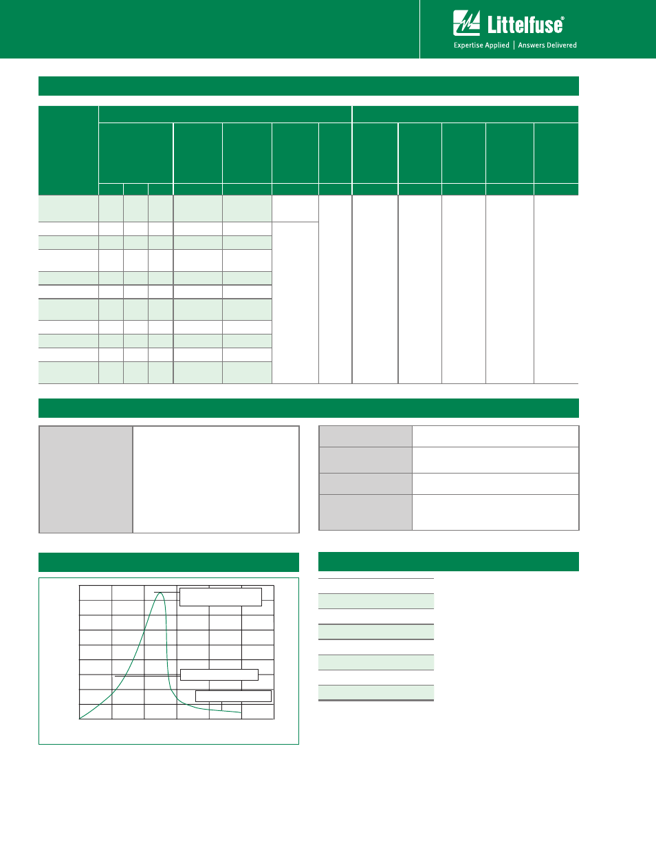
Electrical Characteristics
V
oltage
(V)
Time (ns)
0
200
400
600
800
1000 1200
Max dynamic breakover
voltage
Hold-over voltage
On-State voltage
Voltage vs. Time Characteristic
@ 1.0 GHz = 0.01 dB
@ 1.4GHz = 0.1 dB
@ 1.8 GHz = 0.53 dB
@ 2.1 GHz = 0.81 dB
@ 2.45 GHz= 1 dB
@ 2.8 GHz = 1.2 dB
@ 3.1 GHz = 1.5 dB
@ 3.5 GHz = 2.1 dB
Typical Insertion Loss