Applications and wiring – Factory Direct Hardware Von Duprin CX9947EO3 User Manual
Page 13
14
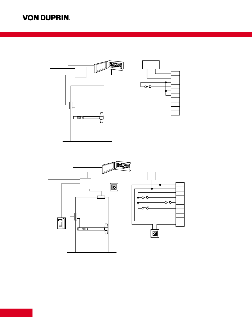
Applications and Wiring
Legend: + 24 = 24 Volt DC; GND = Ground; SC = Signal Common; FA = Fire Alarm (input); DPS = Door Position Switch; El = External Inhibit; (input) CM+ = Communication Line;
CM- = Communication Line; NO = Normally Open External Alarm; C = Common External Alarm.
Basic Chexit single door application configuration consists of the Chexit
device, power transfer and PS873 power supply. Using this setup, the
Chexit will delay egress when armed and act as a normal exit device
when turned off.
120 VAC
3 x 14 ga.
To Fire Alarm
2 x 18 ga.
Junction
Box
EPT-10
PS871/873
Power Supply
PS871/873
Power Supply
Cable
2 x 12 ga.
2 x 18 ga.
2 x 12 ga.
Gnd
Gnd
+24
+24
SC
FA
DPS
EI
CM+
CM–
NO
C
Chexit
Cable
Red
Black
White
Yellow
Orange
Green
Gray
Violet
Blue
Brown
Fire Alarm
120 VAC
3 x 14 ga.
To Fire Alarm
2 x 18 ga.
Junction
Box
EPT-10
Horn
PS871/873
Power Supply
PS871/873
Power Supply
Cable
2 x 12 ga.
6 x 18 ga.
2 x 18 ga.
(input)
Gnd
Gnd
+24
+24
SC
FA
DPS
EI
CM+
CM–
NO
C
Chexit
Cable
Red
Black
White
Yellow
Orange
Green
Gray
Violet
Blue
Brown
Fire Alarm
Card Reader
Door Position Switch
Horn
2 x 12 ga.
2 x 18 ga.
2 x 18 ga.
Card
Reader
(Inside or
Outside)
+
–
Chexit Single Door with Options — The Chexit is used as an access
control device. The card reader allows access. Also shown in this
application is an external horn and door position switch. The auxiliary
horn is used for increased volume in remote locations. Using a door
position switch gives added security to the opening in case the door
is not reclosed.
With the Chexit disarmed, the opening functions as a normal exit device.
If card readers are required on both sides of the door, the normally
closed contacts of the readers should be wired in series.
PS873
PS873
PS873
PS873