P.i.p, I. reset switch, J. dual/mono switch – Crown Audio Com-Tech "00 Series" User Manual
Page 9: Module, Input sensitivity switch, L. level controls, M. balanced barrier block inputs, N. output mode switches, O. output barrier block
Page 9
Com-Tech 200/400/800/1600 Power Amplifiers
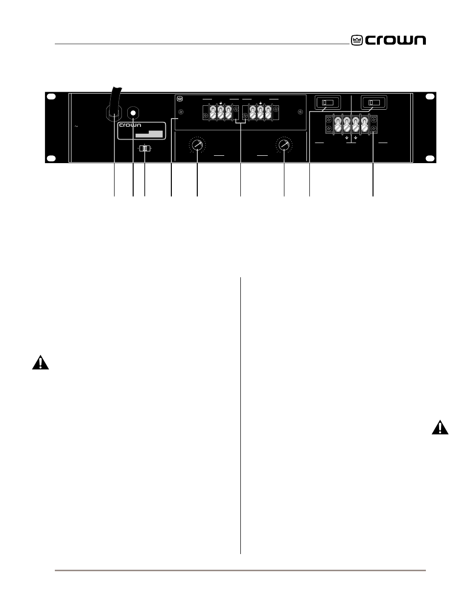
Fig. 2.2 Rear Facilities
I. Reset Switch
This reset switch is used to reset the circuit breaker
that protects the power supplies from overload (see
Sections 4.3.4 and 4.4).
J. Dual/Mono Switch
Slide this switch to the center for Dual (two-channel)
mode, to the left for Parallel-Mono mode or to the right
for Bridge-Mono mode.
WARNING: Do not change this
switch unless the amplifier is turned off. Do not attempt
to use the Bridge-Mono or Parallel-Mono modes unless
both output mode switches (N) are set the same.
Also,
be sure to follow the installation requirements for each
mode (see Section 3.3.1).
K.
P.I.P.
Module
The standard
P.I.P.-BB is included with your amplifier.
It provides barrier block input connectors. Other
P.I.P.
modules can be used in place of the
P.I.P.-BB to pro-
vide additional features that customize the amplifier for
different applications (see Section 8 for available
P.I.P.
modules).
❑ Input Sensitivity Switch
The three position input sensitivity switch located in-
side the amplifier is accessed by removing the
P.I.P.
module. It is set at the factory to 0.775 volts for stan-
dard 1 kHz power into 8 ohms. It can also be set to
0.775 volts for standard 1 kHz output in 70 volt mode,
or a standard voltage gain of 26 dB (see Section 4.4).
L. Level Controls
Each channel’s output level can be adjusted accu-
rately using the 22 position detented level controls on
the back panel. A Lexan cover is also included that
can be used to prevent tampering (see Section 4.4).
M. Balanced Barrier Block Inputs
The
P.I.P.-BB is included in the standard configuration.
It provides a balanced barrier block with three termi-
nals for each input channel. (XLR connectors are also
available—see Section 8.1.)
N. Output Mode Switches
The output mode switches are used to configure each
channel independently for either 8/4 ohm loads or
70 volt (“constant voltage”) lines.
WARNING: Do not
change these switches unless the amplifier is off. Do
not attempt to use the Bridge-Mono or Parallel-Mono
modes unless these switches are set the same.
Also,
be sure to follow the special installation requirements
for each mode (see Section 3.3.1).
O. Output Barrier Block
A barrier block with four terminals is provided for out-
put connection. Output wiring will vary depending on
the selected dual/mono mode and whether 70 volt out-
put will be used (see Section 3.3.1).
BB
Programmable
Input Processor (P.I.P.)
–
+
C H - 2 I N P U T
–
+
C H - 1 I N P U T
PUSH TO RESET
CAUTION: TURN OFF AMPLIFIER
BEFORE CHANGING THIS SWITCH!
DUAL
BRIDGE
MONO
PARALLEL
MONO
CAUTION:
BOTH CHANNELS MUST
BE CONFIGURED THE SAME (8/4 OHM
OR 70 VOLT) BEFORE USING EITHER
BRIDGE- OR PARALLEL-MONO MODE.
MODEL: COM-TECH 200
AC VOLTS: 120 AMPS: 3.5 60 Hz
RATED OUTPUT: 150 W/CH INTO 4 OHMS
AT 1 KHz WITH 0.1% OR LESS THD.
MAXIMUM OUTPUT: 200 W/CH INTO 4
OHMS AT 1 KHz WITH 0.1% OR LESS THD.
MODEL: COM-TECH 400 SERIES
AC VOLTS: 120 AMPS: 5.5 60 Hz
REFER TO OWNER'S MANUAL K80636-2
FOR FIRE PROTECTIVE SIGNALING USE.
REFER TO USER'S MANUAL K80548-9
FOR FIRE PROTECTIVE SIGNALING USE.
0
dB
.5
1
2
3
4
5
6
7
8
9
10
11
13
15
17
19
21
25
32
∞
0
dB
.5
1
2
3
4
5
6
7
8
9
10
11
13
15
17
19
21
25
32
∞
REG. U.S. PAT. OFF.
4,330,809
4,611,180
THIS AMPLIFIER IS EQUIPPED WITH SELECTABLE INPUT SENSITIVITY. REMOVE P.I.P. MODULE TO ACCESS SENSITIVITY SWITCH.
CH-2
CH-1
INPUT ATTENUATION
+
+
70
VOLT
8/4
OHM
70
VOLT
8/4
OHM
CH-2 OUTPUT
CH-1 OUTPUT
BRIDGE-MONO:
1) TURN AMPLIFIER
OFF. 2) SET DUAL/MONO SWITCH TO
BRIDGE-MONO. 3) OUTPUT ACROSS “
+
”
TERMINALS ONLY (CH-1 IS POSTIVE).
PARALLEL-MONO:
1) TURN AMPLIFIER
OFF. 2) SET DUAL/MONO SWITCH TO
PARALLEL-MONO. 3) ADD JUMPER (14 GAGE
OR LARGER) ACROSS THE “
+
” TERMINALS
4) OUTPUT ACROSS CH-1 TERMINALS ONLY.
IMPORTANT:
CLASS 1 OUTPUT
WIRING REQUIRED.
®
INTERNATIONAL, INC.
ELECTRONIC EQUIPMENT
ELKHART, IN 46517
MADE IN U.S.A.
SERIAL NUMBER
0000
000000
PR
ESS
R E S ET
H
J
L
K
O
M
I
L
N