Input wiring tips, Fig. 3.11 unbalanced rfi filters, Fig. 3.12 balanced rfi filters – Crown Audio Com-Tech "00 Series" User Manual
Page 18
Page 18
Com-Tech 200/400/800/1600 Power Amplifiers
4 kHz
10 kHz
40 kHz
100 kHz
Frequency
dB
0
–10
–20
A
B
C
6 dB/octave
12 dB/octave
To
Amp
GND
To
Amp
GND
To
Amp
GND
Source
1.8 K
Ω
.003
f
µ
.015
f
µ
.018
f
µ
3.9 mH
5 mH
600
Source
Ω
R
600
Source
Ω
R
A
C
B
Note: A low source impedance (R) can be
increased to 600 by an appropriate resistor.
Ω
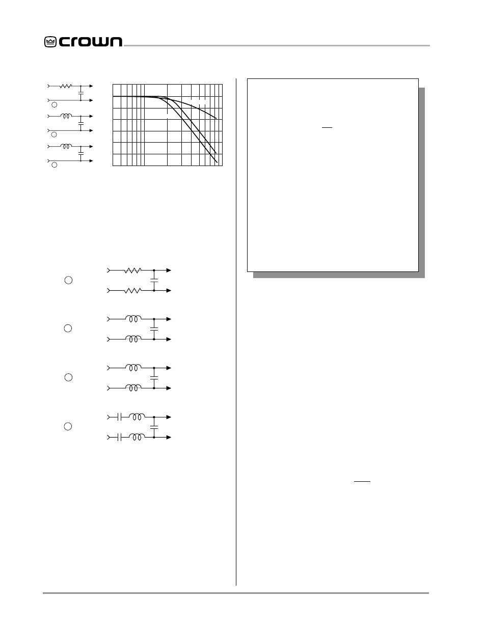
Fig. 3.11 Unbalanced RFI Filters
high frequencies. Extremely high RF levels can also
cause your amplifier to prematurely activate its protec-
tion circuitry, resulting in inefficient operation. RF can
be introduced into a signal by local radio stations and
+
–
Balanced In
910
Ω
.003
f
µ
.015
f
µ
.018
f
µ
1.8 mH
2.5 mH
A
C
B
.015
f
µ
1.8 mH
D
Balanced Out
+
–
910
Ω
1.8 mH
2.5 mH
1.8 mH
+
–
Balanced In
Balanced Out
+
–
+
–
Balanced In
Balanced Out
+
–
+
–
Balanced In
Balanced Out
+
–
0.47 Film
0.47 Film
Fig. 3.12 Balanced RFI Filters
from the bias signal of many tape recorders. To pre-
vent high levels of input RF, install an appropriate low-
pass filter in series with the input signal. Some
examples of unbalanced wiring for low-pass filters are
shown in Figure 3.11.
For balanced input wiring, use an example from Figure
3.12. Filters A, B, and C correspond to the unbalanced
filters shown in Figure 3.11. Filter D also incorporates
the subsonic filter in Figure 3.10.
Tip:
The standard
P.I.P.-BB has plenty of space on its
circuit board for the addition of input filter circuitry.
Another problem to avoid is
ground loops
. These are
undesirable currents that flow in a grounded system
and usually cause hum in the output. A common
source of ground loop problems is the placement of
input cables parallel to power cables or near power
transformers. A ground loop can occur when the mag-
netic field generated by the 50/60 Hz alternating cur-
rent in the power cable or transformer is induced into
the input cables. To prevent this, you can lace the in-
put cables along their length. (Lacing cables helps re-
duce magnetically induced current by minimizing the
cross-sectional area between conductors which could
bisect a magnetic field.) It is also very important to lo-
cate input cables away from power cables and trans-
formers.
Ground loops often occur when the input and output
grounds are tied together. DO NOT CONNECT THE
INPUT AND OUTPUT GROUNDS TOGETHER. Tying
the grounds together can also cause
feedback oscilla-
tion
from the load current flowing in the loop. To avoid
this problem, use proper grounding, isolate the inputs,
and isolate other common AC devices.
3.3.3 Output Connection
Consider the power handling capacity of your load be-
fore connecting it to the amplifier. Crown is not liable
for damage incurred at any time due to overpowering.
Fusing loudspeaker lines is highly recommended (see
Section 3.3.4). Also, please pay close attention to Sec-
Input Wiring Tips
1. Use only shielded cable. Cables with
higher density shields are better. Spiral
wrapped shield is not recommended.
2. When using unbalanced lines, keep the
cables as short as possible. Avoid cable
lengths greater than 10 feet (3 meters).
3. Do not run signal cables together with
high-level wiring such as loudspeaker wires
or AC cords. This reduces the chance of
hum or noise being induced into the input
cables.
4. Turn the entire system off before chang-
ing connections. Turn level controls down
before powering the system back up. Crown
is not liable for damage incurred when any
transducer or component is overdriven.