3 protection systems – Crown Audio Com-Tech "00 Series" User Manual
Page 23
Page 23
Com-Tech 200/400/800/1600 Power Amplifiers
4.3 Protection Systems
Com-Tech amplifiers provide extensive protection and
diagnostics capabilities. Protection systems include
ODEP, “standby” and an AC circuit breaker. These
features provide protection under any conditions.
4.3.1
ODEP
Crown invented
ODEP to solve two long-standing
problems in amplifier design: to prevent amplifier shut-
down during demanding operation, and to increase
the efficiency of the output circuitry.
To do this, Crown established a rigorous program to
measure the
safe operating area (SOA) of each output
device before installing it in an amplifier. Next, Crown
designed intelligent circuitry to simulate the instanta-
neous operating conditions of the output devices. Its
name describes what it does: Output Device Emula-
tion Protection or
ODEP. In addition to simulating the
operating conditions of the output devices, it also com-
pares their operation to their known SOA. If
ODEP sees
that more power is about to be asked of the output de-
vices than they are capable of delivering under the
OFF
OFF
OFF
There is no power to the amplifier. Possible reasons: (1) The amplifier’s Enable switch is off. (2) The
amplifier is not plugged into the power receptacle. (3) The AC mains circuit breaker has been tripped.
(4) The amplifier’s back panel circuit breaker has been tripped. (5) The amplifier’s low-voltage power
supply fuse has blown.
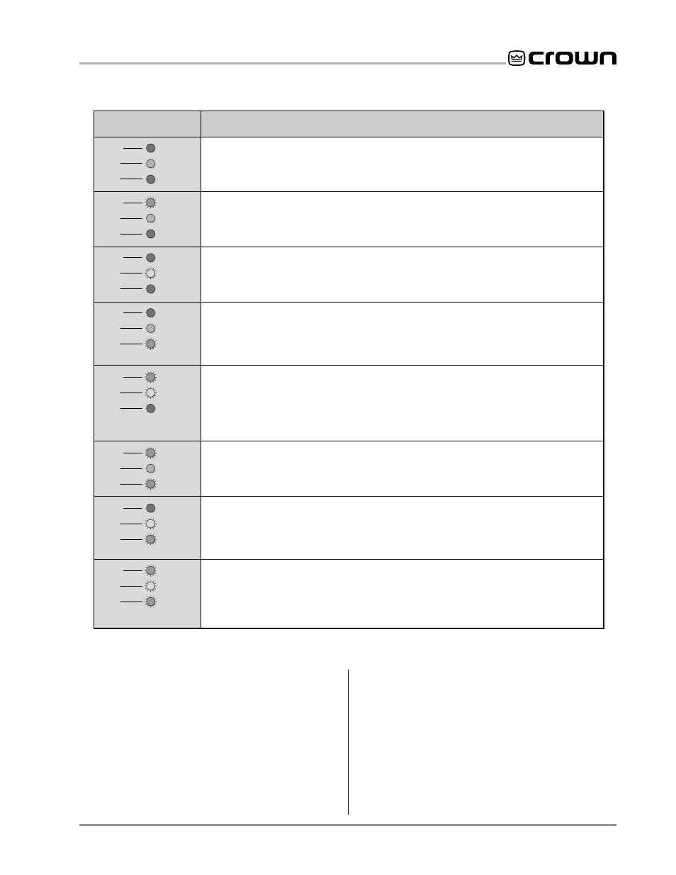
Indicator Status
Amplifier Condition
Normal operation for a channel with NO output. Possible reasons: (1) There is no input signal.
(2) The channel’s level control is turned down.
Normal operation with an input signal. The signal presence indicator (SPI) will flash to show that
an audio signal is present.
The channel’s output is exceeding 0.05% distortion. The input signal level is too high, and IOC
is reporting either an input overload or output clipping.
No output: The amplifier channel is in standby mode. Possible reasons: (1) The DC/low-frequency
protection circuitry has been activated. (2) The fault protection circuitry has been activated after sensing
heavy common-mode current. (3) The transformer thermal protection circuitry has been activated.
ODEP limiting has been activated. Possible reasons: (1) The amplifier’s air filters are blocked and
need to be cleaned. (2) There is insufficient cooling because of inadequate air flow or air that is too hot.
(3) The load impedance for the channel is too low because the output is shorted or the amplifier is
driving too many loudspeakers for the selected dual/mono mode. (4) The amplifier channel is
continuously being driven to very high output levels.
ODEP limiting is about to begin. Possible reasons: (1) The amplifier’s air filters are blocked and need
to be cleaned. (2) There is insufficient cooling because of inadequate air flow or air that is too hot.
(3) The load impedance for the channel is too low because the output is shorted or the amplifier is
driving too many loudspeakers for the selected dual/mono mode. (4) The amplifier channel is
continuously being driven to very high output levels.
ODEP
IOC
SPI
ON
OFF
OFF
ODEP
IOC
SPI
ON
OFF
Active
ODEP
IOC
SPI
ON
ON
Active
ODEP
IOC
SPI
ON
ON
OFF
ODEP
IOC
SPI
OFF
OFF
Active
ODEP
IOC
SPI
Channel 2 only: The amplifier is in Parallel-Mono mode and has output. The channel 2 IOC
indicator always turns on when the amplifier’s dual/mono switch is moved to the Parallel-Mono position.
No output: The amplifier channel is in standby mode. Possible reasons: (1) The amplifier has just
been turned on and is still in the four second turn-on delay. (2) A P.I.P. module such as an IQ-P.I.P.
or the P.I.P.-UL1711 has turned off the channel’s high-voltage supply.
OFF
ON
OFF
ODEP
IOC
SPI
OFF
ON
Active
ODEP
IOC
SPI
OR
Channel 2 only: The amplifier is in Parallel-Mono mode with no output. The channel 2 IOC
indicator always turns on when the amplifier’s dual/mono switch is moved to the Parallel-Mono position.
OR
Fig. 4.1 ODEP, IOC and Signal Presence Indicator States