Twin-lead shielded cable, Single-conductor coax or twisted pair – Crown Audio Com-Tech "00 Series" User Manual
Page 17
Page 17
Com-Tech 200/400/800/1600 Power Amplifiers
tween the positive (+) terminals of both channels.
CAUTION: When Parallel-Mono wiring is installed, do
not attempt to operate in Dual or Bridge-Mono mode
until the wiring is removed (especially the jumper wire).
Failure to do so will result in high distortion and exces-
sive heating.
3.3.2 Input Connection
The balanced inputs have a nominal impedance of
20 K ohms (10 K ohms unbalanced) and will accept
the line-level output of most devices. The factory-in-
stalled P.I.P.-BB provides a balanced three-terminal
input barrier block for each channel (see Figure 2.2).
Optional
P.I.P. modules like the P.I.P.-FX, P.I.P.-FXQ
and P.I.P.-FPX can provide female XLR connectors,
phone jacks and phono (RCA) connectors. Various
P.I.P.s are also available which provide a wide range
+
–
INPUT
+
–
INPUT
2-wire line cord
(or battery power)
Note: If two or more channels with
the same input ground reference
are driven from the same
floating source, connect
only one shield to the
source chassis.
Floating
source
–
+
3-wire grounded line cord
(or other ground connection)
Output
Shield not connected
at this end
Grounded
source
–
+
Output
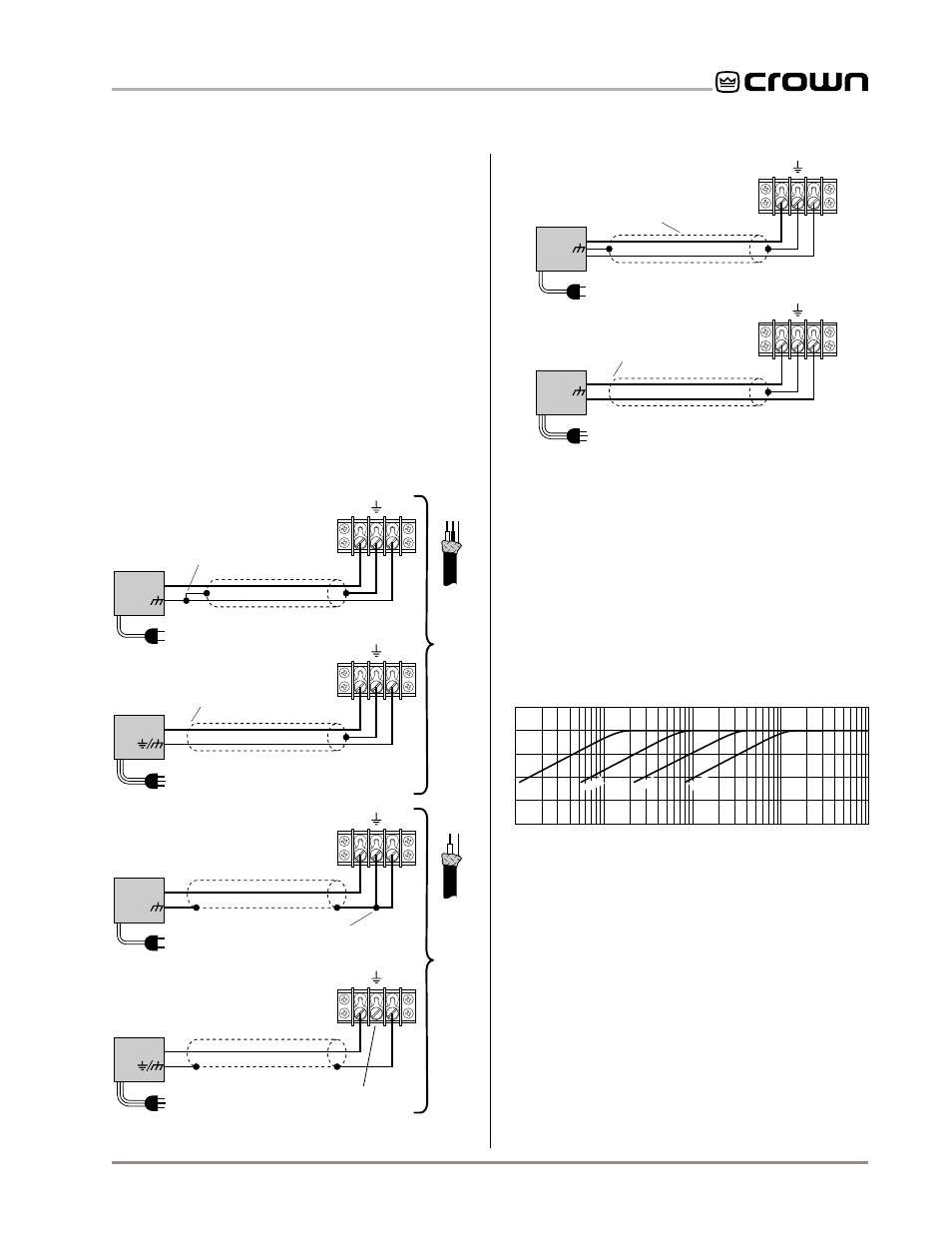
Fig. 3.9 Balanced Input Wiring
Sometimes large
subsonic
(subaudible)
frequencies
are present in the input signal. These can damage
loudspeakers or step-down transformers by overload-
ing or overheating them. To attenuate such frequen-
cies, place a capacitor in series with the input signal
line. The graph in Figure 3.10 shows some capacitor
values and how they affect frequency response. Use
only low-leakage capacitors.
Another problem to avoid is large levels of
radio fre-
quencies
or RF in the input signal. Although high RF
levels may not pose a threat to the amplifier, they can
burn out tweeters or other loads that are sensitive to
of input signal processing features (see Section 8).
Proper input wiring depends on two factors:
(1) whether the input signals are balanced or unbal-
anced, and (2) whether the signal source floats or has
a ground reference. The following illustrations provide
examples of recommended connection techniques for
each type of signal source.
S O L V I N G I N P U T P R O B L E M S
Fig. 3.8 Unbalanced Input Wiring
+
–
Twin-lead shielded cable
+
–
INPUT
2-wire line cord
(or battery power)
Output
Floating
source
Shield connected
to ground terminal
+
–
INPUT
3-wire grounded line cord
(or other ground connection)
Shield not connected
at this end
Grounded
source
3-wire grounded line cord
(or other ground connection)
Input ground
terminal not used
INPUT
Grounded
source
Single-conductor coax
or twisted pair
+
Output
+
–
INPUT
+
2-wire line cord
(or battery power)
Output
Floating
source
Shield connected to both
negative (–) and ground
input terminals
+
Output
+
1 Hz
10 Hz
100 Hz
1 kHz
10 kHz
dB
0
–5
–10
–15
1 f
µ
.1 f
µ
.05 f
.01 f
µ
µ
Frequency
Fig. 3.10 Subsonic Filter Capacitor Values