Use good connectors – Crown Audio Com-Tech "00 Series" User Manual
Page 19
Page 19
Com-Tech 200/400/800/1600 Power Amplifiers
40
30
20
15
10
9
8
7
6
5
4
3
2
1
2
5
10
20
50
100
.04
.06
.1
.2
.4
.6
1
2
4
6
10
20
40
5
10
20
50
1
2
100
200
500
1000
2000
5000
8000
5000
1000
500
100
50
10
5
1
.5
.1
.05
.01
#28
#26
#24
#22
#20
#18
#16
#14
#12
#10
#8
#6
#4
#2
#0
#00
#0000
R
LOAD
RESISTANCE
(ohms)
L
R
R
DAMPING
FACTOR
L
S
R
SOURCE
RESISTANCE
(ohms)
S
2-COND.
CABLE
(feet)
ANNEALED
COPPER
WIRE
(AWG)
(ohms/1000 ft.)
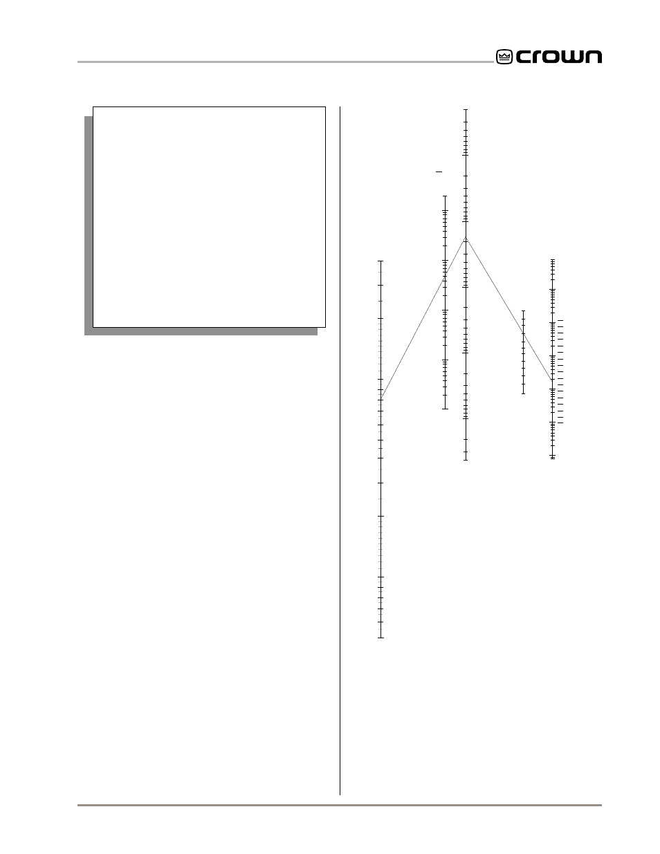
Example Shown:
R = 8 ohms; R = 0.016 ohms or D.F. = 500;
Cable Length = 10 ft.; answer: #8 wire
L
S
1
0.5
200
500
1,000
2,000
20,000
5,000
10,000
.01
.001
.02
.004
.006
.002
.0004
.0006
.0002
0.6
0.7
0.8
1.5
0.9
tion 4.1,
Precautions.
You should always install loudspeaker cables of suffi-
cient gauge (wire thickness) for the length used. The
resistance introduced by inadequate output cables
will reduce the amplifier’s power to and motion control
of the loudspeakers. The latter problem occurs be-
cause the damping factor decreases as the cable re-
sistance increases. This is very important because the
amplifier’s excellent damping factor can be easily ne-
gated by using insufficient cable.
Use the nomograph in Figure 3.13 and the following
procedure to find the recommended wire gauge (AWG
or American Wire Gauge) for your system.
1. Note the load resistance of the loudspeakers con-
nected to each channel of the amplifier. If you are using
70 volt output, be sure to determine the load resistance of
the step-down transformers (Crown’s constant voltage
computer can help with this, see Section 8.3). Mark this
value on the “Load Resistance” line of the nomograph.
2. Select an acceptable damping factor and mark it on
the “Damping Factor” line. Your amplifier can provide an
excellent damping factor of 1,000 from 10 to 400 Hz in
Stereo mode with an 8 ohm load. In contrast, typical
damping factors are 50 or lower. Higher damping factors
yield lower distortion and greater motion control over the
loudspeakers. A common damping factor for commercial
applications is between 50 and 100. Higher damping fac-
tors may be desirable for live sound, but long cable
lengths often limit the highest damping factor that can be
achieved practically. (Under these circumstances,
Crown’s
IQ System is often used so amplifiers can be eas-
ily monitored and controlled when they are located very
near the loudspeakers.) In recording studios and home
hi-fi, a damping factor of 500 or more is very desirable.
Use Good Connectors
1. To prevent possible short circuits, do not
expose the loudspeaker cable connectors.
2. Do not use connectors that might acciden-
tally tie two channels together when making or
breaking connections (for example, a stan-
dard three-wire stereo phone plug).
3. Connectors that can be plugged into AC
power receptacles should never be used.
4. Connectors with low current-carrying ca-
pacity should not be used.
5. Connectors with any tendency to short
should never be used.
3. Draw a line through the two points with a pencil, and
continue until it intersects the “Source Resistance” line.
4. On the “2-Cond. Cable” line, mark the length of the
cable run.
5. Draw a pencil line from the mark on the “Source Resis-
tance” line through the mark on the “2-Cond. Cable” line,
and on to intersect the “Annealed Copper Wire” line.
6. The required wire gauge for the selected wire length and
Fig. 3.13 Wire Size Nomograph