2 facilities, Odep, A. filter grille – Crown Audio Com-Tech "00 Series" User Manual
Page 8: B. dust filter, Indicators, E. signal presence indicators (spi), F. enable indicator, G. enable switch, H. power cord
Page 8
Com-Tech 200/400/800/1600 Power Amplifiers
2 Facilities
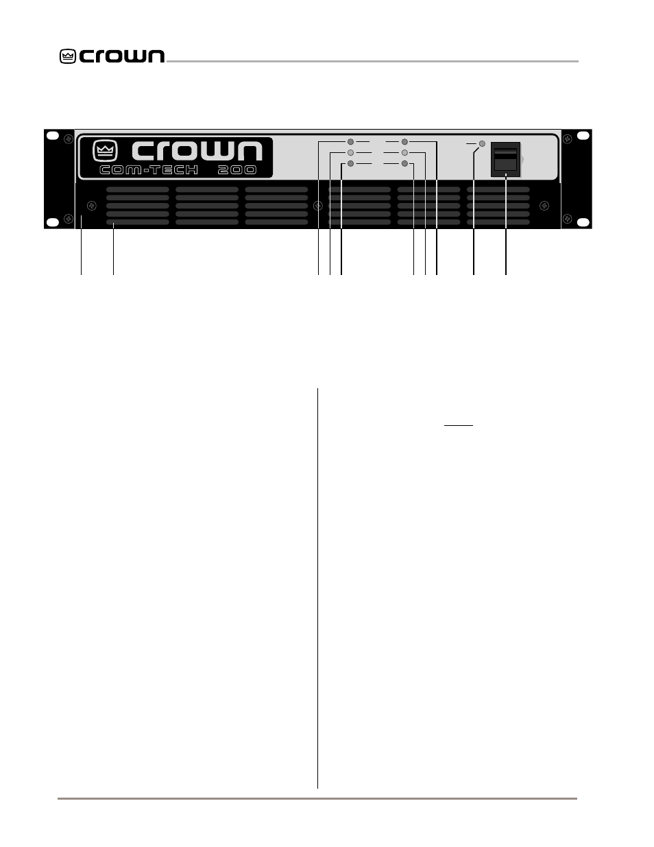
A. Filter Grille
A metal grille supports and protects the dust filter (B).
To clean the dust filter, detach the grille by removing
the screws that fasten it in place.
B. Dust Filter
The dust filter removes large particles from air drawn
by the cooling fan. (The fan is an option for 120 VAC,
60 Hz
Com-Tech 200s .) Check the filter regularly to
prevent clogging (see Section 4.5).
C.
ODEP
Indicators
During normal operation of the Output Device Emula-
tion Protection circuitry, these green indicators glow
brightly to show the presence of reserve thermal-dy-
namic energy. They dim proportionally as energy re-
serves decrease. In the rare event that energy
reserves are depleted, the indicators turn off and
ODEP proportionally limits output drive so the amplifier
can safely continue operating even under severe con-
ditions. These indicators can also help to identify more
unusual operating problems (see Section 4.2).
D.
IOC
Indicators
The yellow
IOC (Input/Output Comparator) indicators
serve as sensitive distortion indicators to provide
proof
of distortion-free performance. Under normal condi-
tions, the indicators remain off. They light up if the out-
put waveform differs from the input by 0.05% or more
(see Section 4.2).
Note: The channel 2 IOC indicator
will stay on in Parallel-Mono mode.
E. Signal Presence Indicators (SPI)
The signal presence indicators flash synchronously
with the amplifier’s audio output (see Section 4.2).
F. Enable Indicator
This indicator lights when the amplifier has been “en-
abled” or turned on, and AC power is available (see
Section 4.2).
G. Enable Switch
This rocker switch is used to turn the amplifier on and
off. When turned on, the output is muted for about four
seconds to protect your system from turn-on tran-
sients. Delay times vary slightly from one unit to the
next, so there is always a certain amount of “random-
ness” in the turn-on timing of multiple units. In addition,
turn-on occurs at zero crossing of the AC waveform, so
Com-Tech amplifiers rarely need a power sequencer.
(To change the turn-on delay time, contact Crown’s
Technical Support Group.) See Section 4.4.
H. Power Cord
All 120 VAC, 60 Hz North American units have a
NEMA 5-15P plug with an integral voltage presence
lamp. These units include a 16 gauge power cord with
Com-Tech 200s and 400s, and a 14 gauge cord with
Com-Tech 800s and 1600s. Other units have an ap-
propriate power cord and plug for the required AC
voltage. Refer to Section 7 for more information on
power usage.
Fig. 2.1 Front Facilities
P OW E R
ODEP
IOC
SPI
ENABLE
CH1
CH2
OFF
A
B
E
D
C
C
D
E
F
G