4 install the wiring – Crown Audio IQ-PIP-USP2_CN User Manual
Page 13
IQ-PIP-USP2/CN
Page 13
IQ-PIP-USP2/CN Reference Manual
Both ribbon cables should run
smoothly from the amplifier to the
PIP
card (see Figure 3.2).
Important:
Be careful when
attaching the ribbon cable to the
connector that the cable is
properly seated before applying
pressure to the connector.
Forcing the cable onto the
connector could cause the keying
tabs, which ensure proper pin
alignment, to break. Connecting
the ribbon cables with improper
pin alignments may result in
damage to the
PIP
.
When both cables are firmly
attached, turn the IQ-PIP-USP2/
CN back to an upright position and
insert into the
PIP
opening in the
back of the amplifier. Take care
while inserting the
PIP
to make
sure you do not crimp, pinch or
stretch the ribbon cables.
8. Tighten the two PIP mounting
screws
until the
PIP
is secured to
the amplifier back panel.
Be sure
to use the supplied star-
washers for good ground
connection.
3.4 Install the Wiring
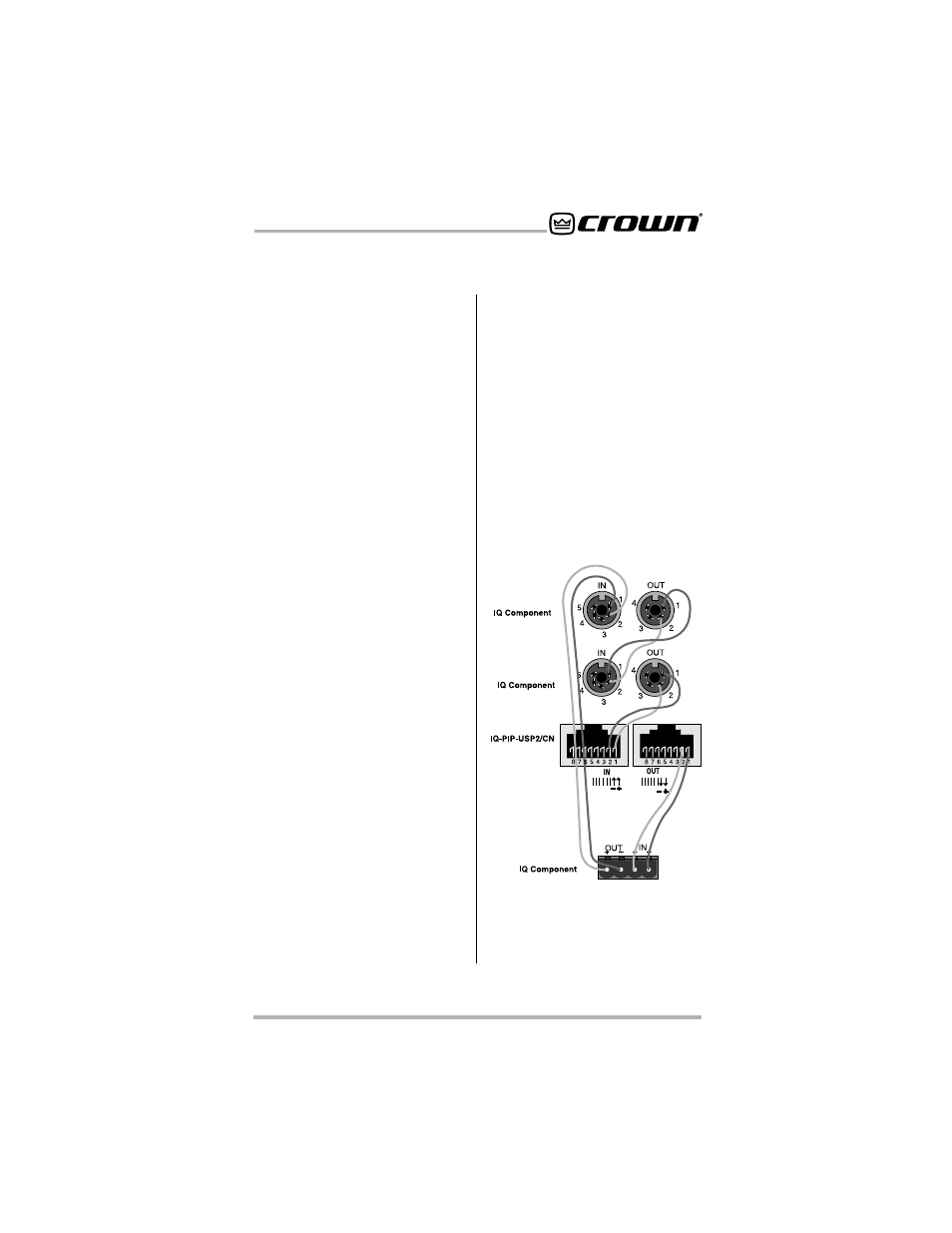
9. Connect the IQ-PIP-USP2/CN to
the IQ system via the IQ Bus.
The
IQ components in a IQ Bus loop
are wired sequentially. The loop
begins and ends with the IQ
interface. The output of one IQ
component “loops” to the input of
the next and so on as shown in
Figure 3.3.
There are three different types of
connectors used for IQ Bus wiring
on IQ components. These include
DIN connectors, screw terminal
plugs, and RJ-45 connectors. The
IQ-PIP-USP2/CN uses RJ-45
connectors that accept standard
RJ-45 plugs like the one shown in
Figure 3.4, allowing the use of
industry-standard straight-thru
type network cables. The left RJ-
45 connector is used for input and
the right RJ-45 connector is used
for output.
Figure 3.3 Standard IQ Bus Wiring
“Loops” from the Output to the Input
of each IQ Component.