En g li sh, Ab b – Factory Direct Hardware Pfister 001-9120 01 Series User Manual
Page 2
EN
G
LI
SH
ENGLISH
4
5
6
3
Thank you for purchasing this Price Pfister product. All Price Pfister products are carefully engineered, and factory tested to
provide long trouble-free use under normal conditions. This product is easy to install using basic tools and our easy to follow
illustrated instructions. If you have any questions regarding this product, call 1-800-Pfaucet (1-800-732-8238).
1 BEFORE PROCEEDING
WARNING: Read all the instructions completely before proceeding. Price Pfister
recommends calling a professional if you are uncertain about installing this product!
This product should be installed in accordance with all local and state plumbing and
building codes.
For optimum performance, a minimum water pressure of 20 PSI [137.8 kPa] is required.
2 SHUT OFF WATER SUPPLY
Locate water supply inlets and shut off the water supply valve. This is usually found
near the water meter. If you are replacing an existing valve, disconnect the old valve
and clean the mounting surface thoroughly. Align and adjust water supply pipes
to recommended dimensions. For new construction install water supply pipes to
recommended dimensions.
3 TOOLS RECOMMENDED
For Iron Pipe Installation:
● PTFE Plumber’s Tape or Thread Sealant
● Slotted screwdriver
● Phillips Screwdriver
● Adjustable wrench
● Pipe Wrench
● Flashlight
● Cloth
For soldered copper and non-standard installations, some additional tools may be
required.
4 HOLE DIMENSIONS
A-Shower head location. B-Shower valve location. C- Spout location
D- Finished Floor
Tub Spout and Shower Outlet holes are to be 1 1/4” diameter. Valve holes are to be
1 3/4” diameter.
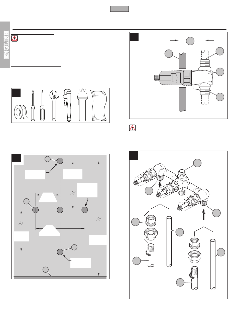
5 VALVE INSTALLATION
CAUTION: Be sure to position the Valve Body (5A) correctly in wall with Valve
Body Inlets (5E) facing down.
Depth (5B) for valve body in wall is measured from the center of the shower outlet
(5D) to the finished wall surface (5C). Minimum distance (5B) is 1
7
/
16
” [37 mm] and
maximum is 2
1
/
8
” [54 mm].
2
C
D
B
A
5A
5E
5B
5D
5C
6A
6A
6B
6E
6C
6C
6D
6D
6’ 6”
(1981 mm)
50”
(1270 mm)
8”
(203 mm)
1
1
/
4
” DIA
(32 mm DIA)
1
1
/
4
” DIA
(32 mm DIA)
A
A
B
B
1
7
/
16
” - 2
1
/
8
”
(37 mm -54 mm)
1
3
/
4
” DIA
(45 mm DIA)
3 Places
4”
(102 mm)
8”
(203 mm)
HOT
COLD
FLOOR