Low & high speeds high speed only, Diagram #8, Diagram #7 – Derale Performance High Output 17" Electric Fan__Black Steel Shroud Kit User Manual
Page 3: Relay, Wiring installation using supplied relay, Electric fan
Derale Performance, Los Angeles, CA
800.421.6288 www.derale.com
Warning: Installation of accessories should only be undertaken by those with mechanical knowledge and are familiar with working on
vehicles. Always use eye protection (goggles, safety glasses or shield). Park the vehicle in a well lit area, on level ground and apply the
parking brake. Only work on a cold vehicle that has been sitting overnight, failure to do so will result in severe burns and injury. Before starting
the vehicle, make sure no tools or any other items are left under hood that could interfere with or be drawn into moving parts of the engine.
Failure to follow instructions can lead to severe damage and personal injury.
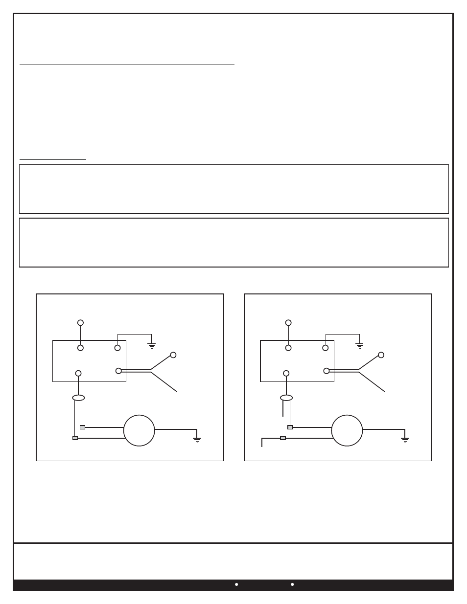
Diagram #8
Chassis
Ground (-)
Blue Fan
Positive (+)
Orange
(Disregard)
30Amp Fuse
Red
30
86
85
87
Green
Orange
Yellow
Black
Chassis
Ground (-)
12 Volt Positive (+)
Battery
12V Switched Power
Manual Switch
or Thermostat
RELAY
Override Circuit
(Optional)
FAN
MOTOR
Black
Grey
Brown
Diagram #7
Chassis
Ground (-)
Blue Fan
Positive (+)
Orange Fan
Positive (+)
30Amp Fuse
Red
30
86
85
87
Green
Orange
Yellow
Black
Chassis
Ground (-)
12 Volt Positive (+)
Battery
12V Switched Power
Manual Switch
or Thermostat
RELAY
Override Circuit
(Optional)
FAN
MOTOR
Black
Grey
Brown
Low & High Speeds
High Speed Only
(Page 3)
WIRING INSTALLATION USING SUPPLIED RELAY
RED Wire - Attach to the Positive side of Battery (+)
BLACK Wire - Attach to a good Chassis ground (-)
BLUE Wire - Reference electric Fan below.
ORANGE Wire - Reference electric Fan below.
YELLOW Wire - Attach to (+) 12V Switched Power (Thermostat or Manual Switch)
GREEN Wire* - (OPTIONAL) Attach to the Positive feed from the A/C Clutch
*This wire will allow you to turn on the Electric Fan every time the vehicles air conditioning is turned on.
If you do not wish to use this option, please disregard the Green wire.
ELECTRIC FAN
12V Switched Power
Manual Switch or Thermostat
USING HIGH SPEED ONLY
(See Diagram #7)
BLACK Wire - Attach to a good Chassis ground (-)
Grey Low Speed Wire - Attach to the Orange positive (+) fan wire on the relay wire harness.
Brown High Speed Wire - Attach to the Blue positive (+) fan wire on the relay wire harness.
USING BOTH LOW & HIGH SPEEDS
(See Diagram #8)
BLACK Wire - Attach to a good Chassis ground (-)
Grey Low Speed Wire - Attach to
.
12V Switched Power (Manual Switch or Thermostat)
Brown High Speed Wire - Attach to the Blue positive (+) fan wire on the relay wire harness.
Important: Both Low speed & High speed wires must have power for high speed function to work
TIPS: Always disconnect vehicles battery before beginning installation involving your vehicles electrical system.
All 12 Volt Positive leads require the use of the appropriate fuse load rating to avoid damage to your vehicles electrical system.
Always insist on using only high quality components (wire, connectors, and switch) for use in installation of your new Derale
Electric Fan Assembly.