Diagram #9, Diagram #8, Relay #1 relay #2 – Derale Performance High Output Dual Rad Fan Assembly User Manual
Page 3
Derale Performance, Los Angeles, CA
800.421.6288
www.derale.com
Blue
Fan Positive (+)
30Amp Fuse
Ignition
Switch
Black
Chassis Ground (-)
Red
30
86
85
87
Green
12 Volt Positive (+)
Battery
180°F
Thermostat Switch
Orange
Diagram #9
Yellow
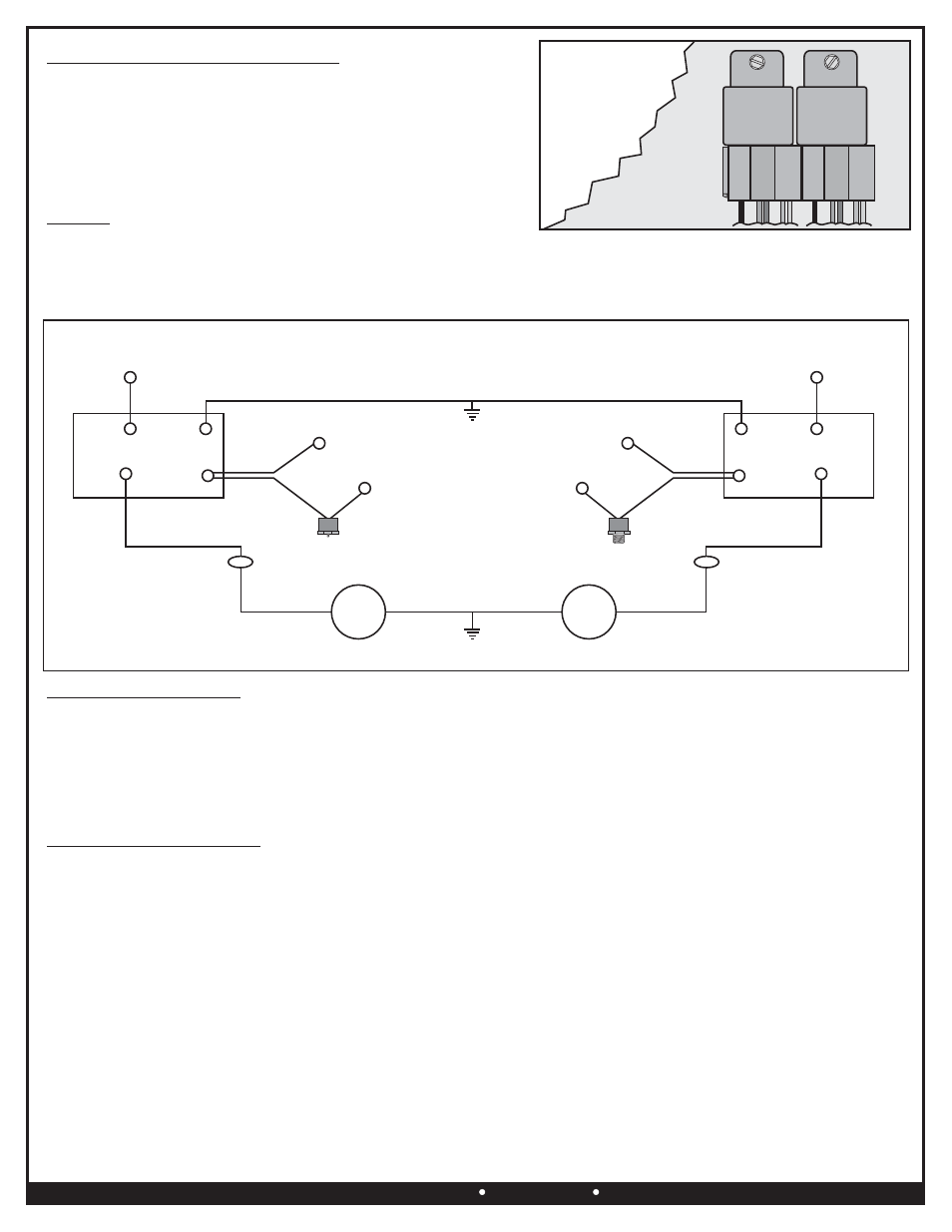
RELAY WIRE HARNESS MOUNTING
1.
Find a convenient location, taking into consideration Thermostat
placement and wire routing requirements. Avoid mounting near
HOT engine components.
2.
Using the Relays as a template, mark and drill two 5/32” holes.
3.
Using the two #10 Sheet Metal Screws provided and a standard
screw driver or 5/16” nut driver, attach the two Relay Harnesses.
(See Diagram #8)
RELAY #1
RELAY #2
FAN MOTOR
Red
86
30
87
85
Ignition
Switch
Green
Override Circuit
(Optional)
190°F
Thermostat Switch
Yellow
30Amp Fuse
Orange
RELAY
#1
Mounting
Surface
RELAY
#2
Diagram #8
FAN MOTOR
Orange
Orange
Blue
Fan Positive (+)
Black
Chassis Ground (-)
Override Circuit
(Optional)
12 Volt Positive (+)
Battery
#1
#2
ELECTRIC FAN WIRING
RELAY HARNESS WIRING
Black Wires -
BOTH
FAN #1
Blue Wire -
ORANGE Wire
FAN #2
Blue Wire -
ORANGE Wire
Black Wires -
BOTH
RELAY #1
Red Wire -
Yellow Wire -
EITHER
Thermostat Switch Wire -
Note:
Orange Wire -
Green Wire - Override Circuit (Optional)
Using the Blue #10 Ring Terminal and #10 Sheet Metal Screw provided, attach
Black wires coming from
the Electric Fans to a good chassis Ground (-).
Using the Blue Butt Connector provided, attach the Blue Positive (+) fan wire to the
on Relay #1.
Using the Blue Butt Connector provided, attach the Blue Positive (+) fan wire to the
on Relay #2.
Using the Blue #10 Ring Terminal and #10 Sheet Metal Screw provided, attach
Black wires coming from
the Electric Fans to a good chassis Ground (-).
Using the Blue 5/16” Ring Terminal provided, attach the Red wire directly to the vehicles Positive (+) battery
terminal.
Using the Blue Butt Connector provided, attach the Yellow Wire to
wire on the 180° Thermostat Switch.
Using the Red Butt Connector, Blue Wire Tap Connector and Wire provided, attach the remaining
Thermostat Switch Wire to a Positive (+) switched ignition source.
If the Yellow Wire is connected to a constant power source (battery) the electric fan will run after the vehicle has been
shut off and could run down the battery.
See Electric Fan Wiring
The Green Wire is designed to work in two different configurations. When used, this will allow the fan to be turned on
regardless of the temperature of the thermostat as it simply overrides all other functions. If you choose to not use this option,
cut any exposed copper and tape or shrink wrap the end of the wire.
(Page 3)
WIRING
Before starting, disconnect the Negative (-) cable on the vehicles battery.
Using the electrical connectors and wire ties provided, follow the directions below. (See Diagram #9)
When extending wires always use the identical gauge wire as provided.
Identify which Relay will be used for Fan #1 and Fan #2 and temporarily mark using a piece of tape and pencil.
WARNING: