Ingalls 35655 User Manual
Ingalls For the car
Part Number 35655
Installation Instructions
ING35655-051605
CAUTION: Observe proper safety and repair procedures for installation of all chassis parts. Some chassis parts require specialized tools and
experience and therefore MUST be installed by a qualified technician otherwise an unsafe vehicle and/or personal injury could result. Wear
safety glasses and other protection.
WARNING: Before beginning, check for any damaged or loose ball joint connections (steering tie rod end and upper and lower ball joints).
Loose connections here indicate the ball joint taper and/or the knuckle tapers are either worn or broken and MUST BE REPLACED. Failure to
replace a damaged or worn steering knuckle may cause loss of steering due to ball joint breakage and will cause the wheel to separate from the
vehicle, possibly resulting in serious personal injury.
NOTE: These parts are intended for use in vehicles with abnormal alignment and are designed to replace the non-adjustable factory equipment.
These parts are not designed for installation on vehicles with suspension and/or steering systems modified for racing, competition or any other
non-standard purpose.
Overview
This kit requires removing the OEM lower front ball joint. The OEM ball joint is re-installed on a sliding plate that
allows camber adjustment.
Removal Instructions
1. Raise front of vehicle in a safe manner and support vehicle on jack stands under the vehicle. The rim/tire
assembly can be removed to aid installation, but it is not necessary.
2. Remove the lower front ball joint from the steering knuckle assembly – remove lock nut and break ball stud
taper free. (It is possible to do this installation without removing the ball joint from the steering knuckle, but
it is more difficult.)
3. Remove the ball joint from the lower control arm assembly – Loosen and remove the 3 M8 bolts and nut
plate.
4. Check the ball joint for damage (worn boot, free play, etc.). If damaged, replace ball joint.
Assembly & Installation Instructions
1. Attach the OE ball joint to the sliding bracket. Insert 3 the M8 bolts up through the bottom so that the flat
washers and lock nuts are on the top side of the ball joint. The heads of the hex bolts must line up with the
scribes provided on the bottom side of the sliding bracket. If the heads of the bolts are not lined up with
scribed they will bind in the slots of the forged base. Torque bolts to 20 ft*lbs.
2. Place the triangular spacer inside the control arm (where the ball joint was mounted).
3. Attach the forged metal base to the top of the control arm. Using 3 M8 bolts with 3 M8 ribbed lock washers
thread them up from the bottom, through control arm and the triangular spacer into the threaded holes in the
forged base. Torque bolts to 20 ft*lbs.
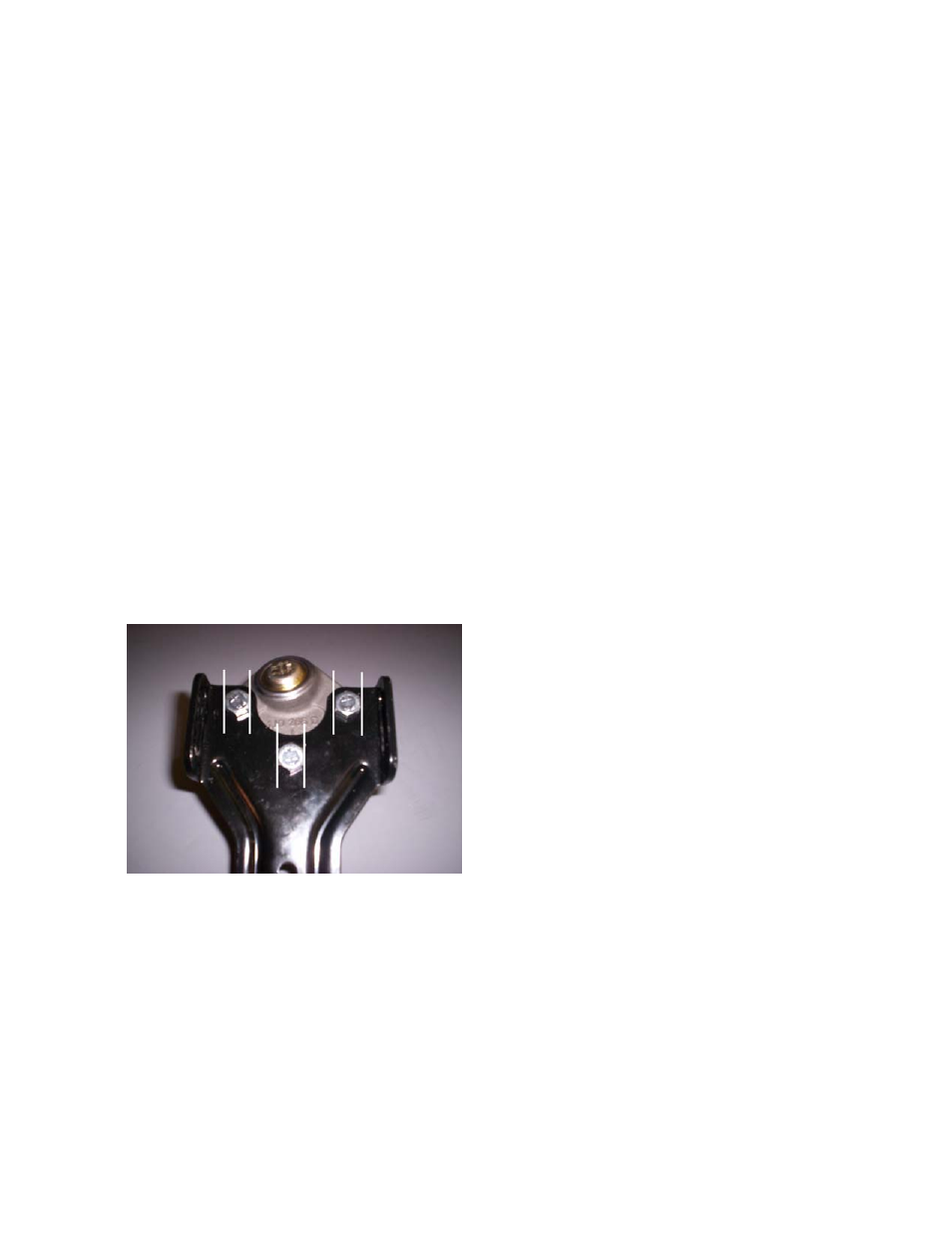
4. Using 3 M8 bolts and 3 M8 ribbed lock washers attach the ball joint/sliding bracket assembly over the forged
base by threading the bolt/lock washers through all 3 slots (2 located on the side and one on the top). Only
snug the bolts, but do not torque at this point.
5. Install ball joint to steering knuckle, torque locking nut to manufacturer specifications.
6. Reinstall the tire wheel assembly, Install alignment equipment and adjust camber by sliding bracket in for
positive adjustment or out for negative adjustment. Using a jack to slightly lift or lower the vehicle to increase
or reduce weight on the wheel will help to allow the assembly to slide.
7. Once the correct position is obtained, torque the 3 M8 bolts between the sliding plate and forged metal base
to 20 ft*lbs to lock the assembly in place.
8. Check and set toe to specifications, road test vehicle and make further adjustments as needed.