Potentiometer input, 4 potentiometer, Input – B&B Electronics DUALCON-3 - Datasheet User Manual
Page 9
DUALCON-3 USERS GUIDE
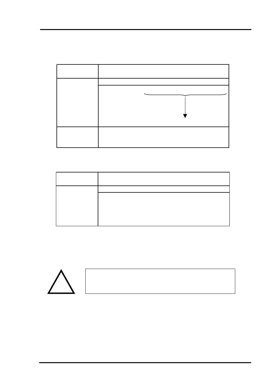
4.1.4 Potentiometer Input
Select the range from the table below and set Switch S1 to the required values.
Potentiometer
Input
1
2
3
4
5
6
7
8
9
10 11 12
2 Wire 0-125R
0
0
0
0
0
0
0
1
1
1
0
1
2 Wire 0-250R
0
0
0
1
2 Wire 0-500R
0
0
1
0
2 Wire 0-625R
0
1
0
0
2 Wire 0-750R
1
0
0
0
2 Wire 0-1K
0
0
1
1
0
0
0
1
1
1
0
1
3 Wire from
0-1K to 0-100K
0
0
0
0
0
1
0
1
1
1
1
0
Switch S1
Then select the required setting from the table below for switch S2
Potentiometer
Input
1
2
3
4
5
6
7
8
9
10 11 12
0
1
0
0
1
0
0
1
0
0
0
1
0
0
1
1
0
0
1
1
0
0
1
0
3 Wire
Potentiometer
Switch S2
2 Wire
Potentiometer
!
! WARNING !
DO NOT OPEN UNIT OR ADJUST SWITCHES WITH
POWER SUPPLY, INPUT OR OUTPUT CONNECTED
Please note that PC Software is available to provide information on
switch settings for your input and output requirements.
IIG-010901 Page
9
See also other documents in the category B&B Electronics Accessories communication:
- USOPTL4DR-LS - Datasheet (2 pages)
- ZXT9-IOA-KIT - Manual (75 pages)
- ADAM-6066 - Manual (272 pages)
- 855-11619--57 - Datasheet (2 pages)
- 851-10904 - Datasheet (2 pages)
- SS-BLT-100PR - Quick Start Guide (1 page)
- ISOCON-6 - Datasheet (2 pages)
- I-7060 - Manual (64 pages)
- AMU864 - Datasheet (2 pages)
- 714FX6-SC_ST - Manual (154 pages)
- 422LP25R - Datasheet (2 pages)
- ZP9D-115RM-LR - Manual (54 pages)
- EKI-6311GN-EU - Manual (56 pages)
- ZZ24D-NA(NB,NC,ND)-SR - Quick Start Guide (4 pages)
- ESCLP-100 - Manual (23 pages)
- 806-39753 - Datasheet (1 page)
- 485SD9RJ - Datasheet (1 page)
- 712FX4-SC_ST - Manual (154 pages)
- 850-18610 - Manual (18 pages)
- ESW208 Series - Datasheet (2 pages)
- VESR321_ML_SL - Quick Start Guide (3 pages)
- OP10 - Datasheet (1 page)
- RT3G-300_310_320_330_340-W - Configuration Manual (79 pages)
- EIRHP305-T - Datasheet (2 pages)
- EIRSP1 - Datasheet (1 page)
- 422TTL33 - Datasheet (2 pages)
- 485DRCI - Quick Start Guide (2 pages)
- I-7021_P - Datasheet (2 pages)
- NTSA-CAT5E - Datasheet (2 pages)
- 485COSR - Datasheet (2 pages)
- 855-10619--57 - Datasheet (2 pages)
- UH401SL_2KV - Datasheet (2 pages)
- 105FXE-SC(ST)-15-POE - Manual (19 pages)
- 102MC-FL_SC_ST - Manual (23 pages)
- CBL00302 - Datasheet (1 page)
- 850-18100--27 - Datasheet (2 pages)
- 850-10953-DC - Datasheet (2 pages)
- ESR904 - Datasheet (2 pages)
- 308TX-N - Datasheet (3 pages)
- 422LP25N - Datasheet (2 pages)
- 708FX2-SC_ST - Datasheet (3 pages)
- MESR321_SL_ML - Datasheet (2 pages)
- SL2736-698 - Quick Start Guide (8 pages)
- I-7188E Series - Datasheet (1 page)
- ANT-PAD58-19 - Datasheet (1 page)