Output configuration, 7 output, Configuration – B&B Electronics DUALCON-3 - Datasheet User Manual
Page 12: Examples
DUALCON-3 USERS GUIDE
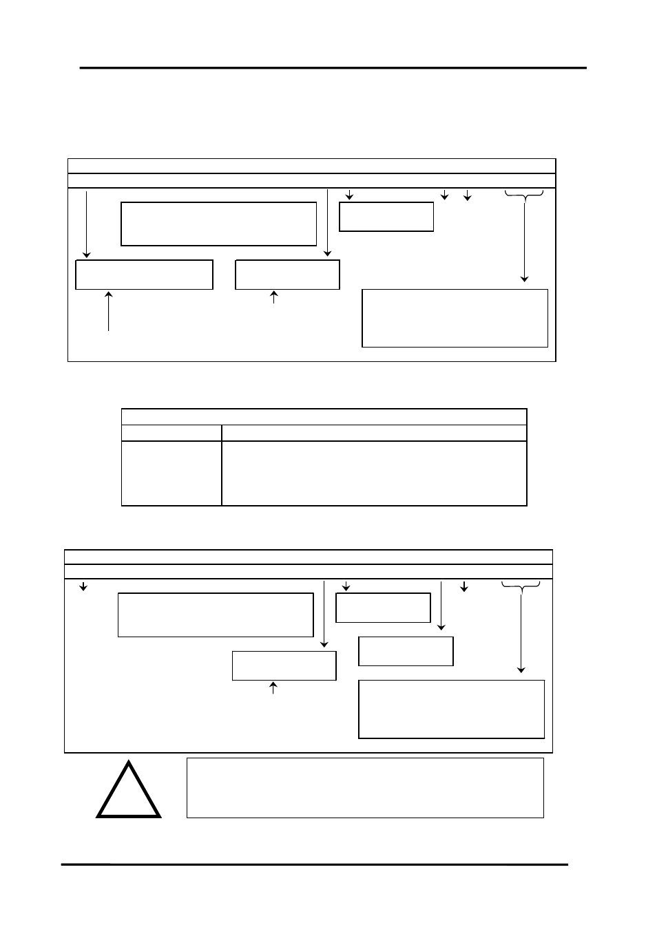
4.1.7 Output Configuration
Select the range for Output 1 from the table below and set Switch S3 to the
required values.
1
2
3
4
5
6
7
8
9
10
11 12
0
1
0
1
0 mA Source
0 Normal
0
1
1
0
1
0
0 mA Sink
1 Inverted o/p
0
1
0
1
1 Voltage
0 Buttons Disabled
High Burnout 0
1 Buttons Enabled
Low Burnout 1
4-20mA / 2-10V
0
0
Output value if fault on input signal
0-20mA / 0-10V
0
1
0-10mA / 0-5V
1
0
Front panel buttons can be disabled to allow
2-10mA / 1-5V
1
1
tamper-proof operation of the unit
Switch S3 - Output Configuration
Examples:
1
2
3
4
5
6
7
8
9
10 11 12
4-20mA Source
1
0
1
0
1
0
0
0
0
0
0
0
0-20mA Source
1
0
1
0
1
0
0
0
0
0
0
1
0-10V
1
0
1
0
1
1
0
0
0
0
0
1
4-20mA Sink
1
1
0
1
0
0
0
0
0
0
0
0
Switch S3 Examples
Repeat the process for Output 2 using the table below for switch S4:
Page
12
IIG-010901
1
2
3
4
5
6
7
8
9
10
11 12
1
0
1
0
1
0 mA Source
0 Normal
1
1
0
1
0
0 mA Sink
1 Inverted o/p
0
1
0
1
1 Voltage
Normal 0
High Burnout 0
Square Root 1
Low Burnout 1
4-20mA / 2-10V
0
0
Output value if fault on input signal
0-20mA / 0-10V
0
1
0-10mA / 0-5V
1
0
2-10mA / 1-5V
1
1
Switch S4 - Output 2 Configuration
Please note that PC Software is available to provide information on
switch settings for your input and output requirements.
! WARNING !
DO NOT OPEN UNIT OR ADJUST SWITCHES WITH
POWER SUPPLY, INPUT OR OUTPUT CONNECTED
!