Connections – B&B Electronics DUALCON-3 - Datasheet User Manual
Page 4
DUALCON-3 USERS GUIDE
3. CONNECTIONS
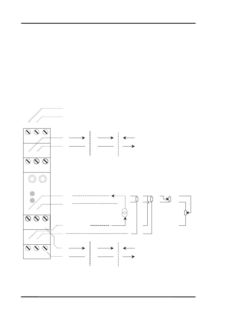
The DUALCON is housed in a compact DIN rail mounting enclosure, with 12
terminals, arranged in 4 rows of 3 terminals. Two rows are at the top of the front
panel and 2 rows are at the bottom. All the sensor input terminals are on the
bottom rows together with the second analogue output, and the power supply and
first analogue output are on the top terminals.
The diagram below shows how to connect all the different input, output and
power supply types.
1K to 100K
3 Wire Pot
1
2
7
9
4
5
6
3
OUTPUT 1
PSU
INPUT
INPUT
2 L
N
+ve
- ve 0-10V 0(4)-20mA
4-20mA Sink
24V Supply
+ve
- ve
24V Tx Supply
Input: mA, Volts, mV, T/C
4-20mA Sink
3 Wire RTD 4 Wire RTD
2 Wire RTD
1
9
7
5
4
3
6
Voltage Source Current Source Current Sink
2-wire
transmitter
10
12
x
x
+ve
12
- ve
10
0-10V 0(4)-20mA
Voltage Source Current Source
OUT2
OUT2
90 – 264VAC
125R to 1K
2 Wire Pot
24V Tx Supply
4-20mA Sink
Current Sink
Page
4
IIG-020901
- USOPTL4DR-LS - Datasheet (2 pages)
- ZXT9-IOA-KIT - Manual (75 pages)
- ADAM-6066 - Manual (272 pages)
- 855-11619--57 - Datasheet (2 pages)
- 851-10904 - Datasheet (2 pages)
- SS-BLT-100PR - Quick Start Guide (1 page)
- ISOCON-6 - Datasheet (2 pages)
- I-7060 - Manual (64 pages)
- AMU864 - Datasheet (2 pages)
- 714FX6-SC_ST - Manual (154 pages)
- 422LP25R - Datasheet (2 pages)
- ZP9D-115RM-LR - Manual (54 pages)
- EKI-6311GN-EU - Manual (56 pages)
- ZZ24D-NA(NB,NC,ND)-SR - Quick Start Guide (4 pages)
- ESCLP-100 - Manual (23 pages)
- 806-39753 - Datasheet (1 page)
- 485SD9RJ - Datasheet (1 page)
- 712FX4-SC_ST - Manual (154 pages)
- 850-18610 - Manual (18 pages)
- ESW208 Series - Datasheet (2 pages)
- VESR321_ML_SL - Quick Start Guide (3 pages)
- OP10 - Datasheet (1 page)
- RT3G-300_310_320_330_340-W - Configuration Manual (79 pages)
- EIRHP305-T - Datasheet (2 pages)
- EIRSP1 - Datasheet (1 page)
- 422TTL33 - Datasheet (2 pages)
- 485DRCI - Quick Start Guide (2 pages)
- I-7021_P - Datasheet (2 pages)
- NTSA-CAT5E - Datasheet (2 pages)
- 485COSR - Datasheet (2 pages)
- 855-10619--57 - Datasheet (2 pages)
- UH401SL_2KV - Datasheet (2 pages)
- 105FXE-SC(ST)-15-POE - Manual (19 pages)
- 102MC-FL_SC_ST - Manual (23 pages)
- CBL00302 - Datasheet (1 page)
- 850-18100--27 - Datasheet (2 pages)
- 850-10953-DC - Datasheet (2 pages)
- ESR904 - Datasheet (2 pages)
- 308TX-N - Datasheet (3 pages)
- 422LP25N - Datasheet (2 pages)
- 708FX2-SC_ST - Datasheet (3 pages)
- MESR321_SL_ML - Datasheet (2 pages)
- SL2736-698 - Quick Start Guide (8 pages)
- I-7188E Series - Datasheet (1 page)
- ANT-PAD58-19 - Datasheet (1 page)