B&B Electronics 850-14200--95 - Manual User Manual
Page 16
13
Mode
Repeater module copper port and loops it
back.
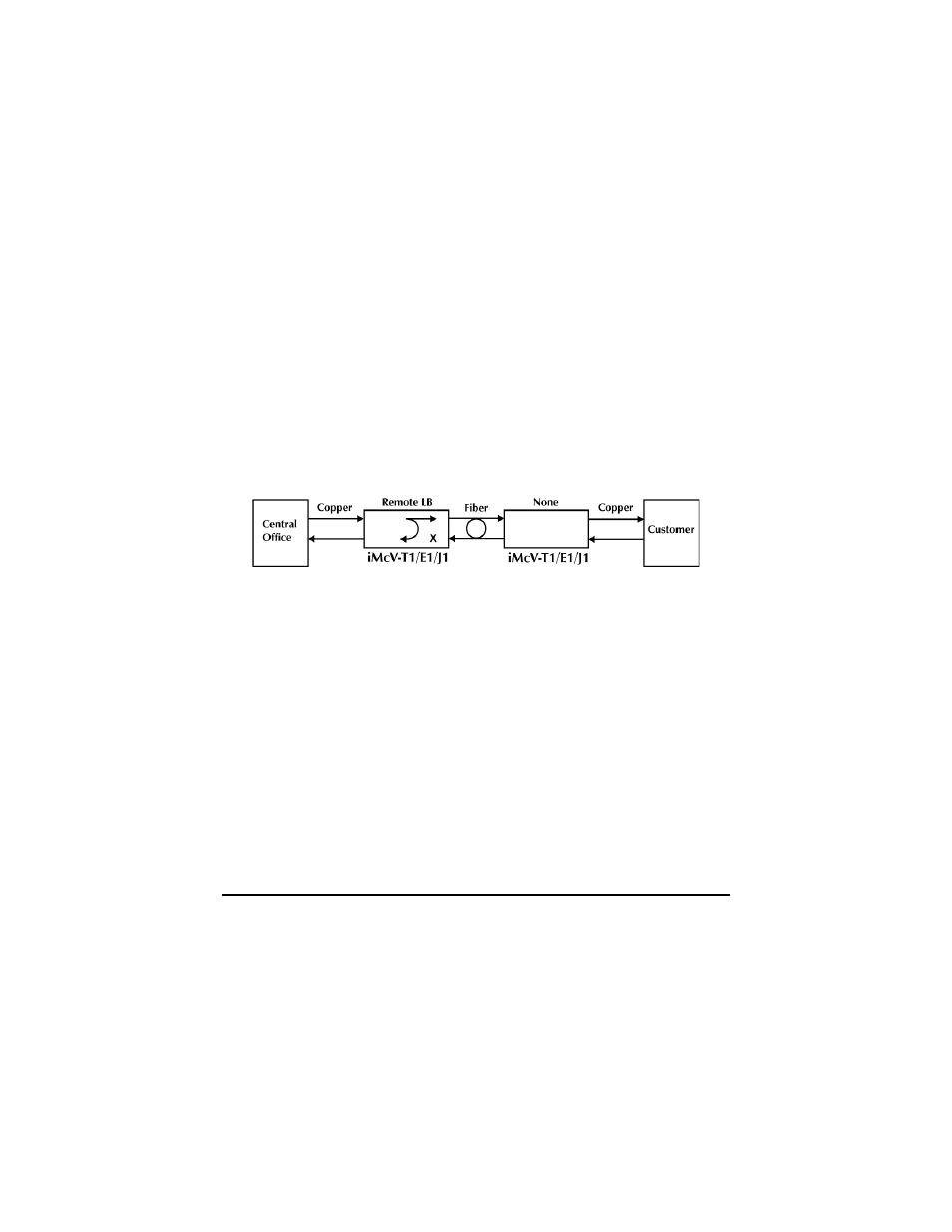
The following illustrations show a typical progression of digital loopback tests;
this series allows the user to individually test each segment of the conversion. To
test the copper segment at the remote location requires the PRBS test described
in the next section.
Local Fiber Loopback Mode
To set the loopback testing mode to Local Fiber Loopback Mode, perform the
following:
1. Set the Local iMcV-T1/E1/J1 Repeater module to Remote Loopback
(DIP Switch S3-3=Off and S3-4=Off)
2. Set the Remote iMcV-T1/E1/J1 Repeater module Loopback to None
(DIP Switch S3-3=On and S3-4=On).
This configuration allows the user to test the path from the CO copper port to the
Local iMcV-T1/E1/J1 Repeater module fiber port and loop it back. The
transmitted data is sent unhindered and the received data is ignored.
Remote Fiber Loopback Mode
To set the loopback testing mode to Remote Fiber Loopback Mode, perform the
following:
1. Set the Local iMcV-T1/E1/J1 Repeater module Loopback to None
(DIP Switch S3-3=On and S3-4=On)
2. Set the Remote iMcV-T1/E1/J1 Repeater module to Local Loopback
(DIP Switch S3-3=Off and S3-4=On).
This configuration allows the user to test the path from the CO copper port to the
Remote iMcV-T1/E1/J1 Repeater module fiber port and loop it back. The
transmitted data is sent unhindered and the received data is ignored.