B&B Electronics 850-18100--27 - Manual User Manual
Page 13
10
Loopback Modes
This feature allows three distinct Loopbacks to be activated either through DIP
Switches or iView
2
Management.
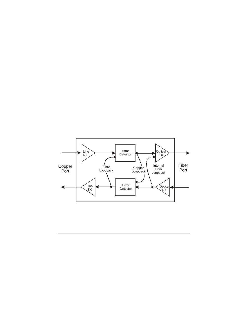
Fiber
Loopback
An analog Loopback at the copper port back to the fiber port.
It copies the received optical signal back to the optical line at
the copper port and continues to drive the copper port, but
can be corrupted by noise on the copper port.
Internal
Fiber
Loopback
A local Loopback at the fiber port. It copies the received
optical signal back to the optical line at a digital point internal
to the unit. It continues to drive the copper port, and normal
copper line monitoring is maintained on the copper port, but
the returning data pattern is not affected.
Copper
Loopback
A remote Loopback to copper port at the fiber driver. It copies
the received copper signal back to the copper port and
continues to drive the fiber port.
By default all Loopbacks are set to OFF for normal data operation.
The following illustrations show the path that a signal takes in each of the
Loopback test modes.
This feature can be controlled by SNMP–Management software (iView
2
) when the
HOST IE-iMcV-T1/E1/J1-LineTerm, TP/SFP module is installed in a managed
chassis.