Recommended footprint, Mounting hole specification, Alternate mounting hardware – B&B Electronics WLNN-EK-DP551 - Product Specification User Manual
Page 31: Figure 7 - recommended pcb footprint, 0 recommended footprint, 1 mounting hole specification, 2 alternate mounting hardware, Airborne dp550 family databook
Airborne DP550 Family Databook
B&B Electronics, Inc.
31
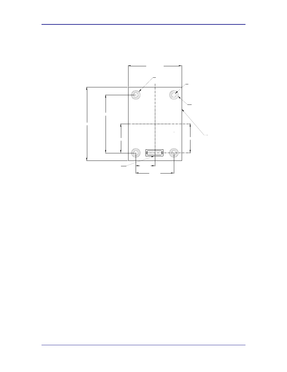
11.0 Recommended Footprint
Figure 7 - Recommended PCB Footprint
15.90mm
Ø5.00mm (X4)
Device Standoff Keepout Area
Ø2.30mm (X4)
Board outline
Dimensions: mm
Tolerance: ± 0.15 (unless noted)
29.60mm MAX
40.60mm MAX
2
1
36
35
Hirose DF12(4.0)-36DP-0.5V
21.00mm
32.00mm
16.00mm
10.50mm
VIEWED FROM TOP
11.1 Mounting Hole Specification
The mounting hole specification is important. It allows for a tight and reliable
friction-based interference between the host PCB and the DP550 stand-off
hardware.
Nominal Diameter:
2.2mm
Tolerance:
+0.15mm/-0.00mm
Host Board Thickness: 0.8mm to 1.6mm
11.2 Alternate Mounting Hardware
B&B does support alternate mounting hardware for the DP550 platform. Please
contact your B&B sales representative for further details.
- USOPTL4DR-LS - Datasheet (2 pages)
- ZXT9-IOA-KIT - Manual (75 pages)
- ADAM-6066 - Manual (272 pages)
- 855-11619--57 - Datasheet (2 pages)
- 851-10904 - Datasheet (2 pages)
- SS-BLT-100PR - Quick Start Guide (1 page)
- ISOCON-6 - Datasheet (2 pages)
- I-7060 - Manual (64 pages)
- AMU864 - Datasheet (2 pages)
- 714FX6-SC_ST - Manual (154 pages)
- 422LP25R - Datasheet (2 pages)
- ZP9D-115RM-LR - Manual (54 pages)
- EKI-6311GN-EU - Manual (56 pages)
- ZZ24D-NA(NB,NC,ND)-SR - Quick Start Guide (4 pages)
- ESCLP-100 - Manual (23 pages)
- 806-39753 - Datasheet (1 page)
- 485SD9RJ - Datasheet (1 page)
- 712FX4-SC_ST - Manual (154 pages)
- 850-18610 - Manual (18 pages)
- ESW208 Series - Datasheet (2 pages)
- VESR321_ML_SL - Quick Start Guide (3 pages)
- OP10 - Datasheet (1 page)
- RT3G-300_310_320_330_340-W - Configuration Manual (79 pages)
- EIRHP305-T - Datasheet (2 pages)
- EIRSP1 - Datasheet (1 page)
- 422TTL33 - Datasheet (2 pages)
- 485DRCI - Quick Start Guide (2 pages)
- I-7021_P - Datasheet (2 pages)
- NTSA-CAT5E - Datasheet (2 pages)
- 485COSR - Datasheet (2 pages)
- 855-10619--57 - Datasheet (2 pages)
- UH401SL_2KV - Datasheet (2 pages)
- 105FXE-SC(ST)-15-POE - Manual (19 pages)
- 102MC-FL_SC_ST - Manual (23 pages)
- CBL00302 - Datasheet (1 page)
- 850-18100--27 - Datasheet (2 pages)
- 850-10953-DC - Datasheet (2 pages)
- ESR904 - Datasheet (2 pages)
- 308TX-N - Datasheet (3 pages)
- 422LP25N - Datasheet (2 pages)
- 708FX2-SC_ST - Datasheet (3 pages)
- MESR321_SL_ML - Datasheet (2 pages)
- SL2736-698 - Quick Start Guide (8 pages)
- I-7188E Series - Datasheet (1 page)
- ANT-PAD58-19 - Datasheet (1 page)