B&B Electronics 850-39950 - Manual User Manual
Page 7
14
Alarm Reset
This feature is available on the fault-tolerant (dual-power supply) model of the
iMediaChassis/3. When one power supply malfunctions, an alarm will sound. A red
alarm reset button, located next to the power connector on the right side of the
power supply, stops this alarm. The LEDs on the management module and the
iView² software both display power supply failures. If a power supply failure occurs,
return the iMediaChassis/3 to IMC Networks for repair or replacement.
Last Gasp Alarm
The iMediaChassis/3 includes the Last Gasp feature, which sends a Trap when the
following occurs:
• Both power supplies malfunction,
• Both power supplies are powered down
• When the AC line fails
Temperature Control
The iMediaChassis/3 includes temperature activated fans and an SNMP temperature
Trap to protect the chassis from overheating.
Temperature Triggered Fans
The iMediaChassis/3 includes temperature triggered fans. When the temperature of
the chassis reaches 40° C, the two fans are activated. You can test the fans operation
by holding the Alarm Reset button down for 4 to 5 seconds. The fans will activate
and then they will turn off when you release the button. If the fans do not activate,
contact IMC Networks.
Temperature SNMP Trap
The management module includes a heat sensor for monitoring the temperature of
the iMediaChassis/3. You can define a threshold for chassis temperature by using
SNMP (refer to the iView² online help for more information about assigning Traps).
When the temperature of the chassis rises above the specified level, the SNMP agent
sends a Trap to the administrator. There is also an LED indicator on the SNMP
Management Module for module temperature (refer to the SNMP Management
Module LEDs section for more information).
3
Installing Management Modules
An SNMP Management Module must be installed in the iMediaChassis/3 to enable
module and chassis management (except when using modules with built-in
management, such as the iMcV-Giga-FiberLinX-II). The SNMP Management module
installs in the management slot located at the bottom left of the chassis. This slot is
only for the management module; do not install application modules such as media
conversion and mode conversion modules in this slot. Double wide modules
installed in Slot 1 will overlap the management slot.
NOTE
The SNMP Management module includes DIP switches. These switches are
factory set and must not be moved.
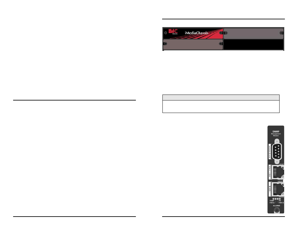
SNMP Management Module LEDs
Each SNMP Management Module features several LEDs.
The LED functions are:
• LNK/ACT
Glows green when a link is established on port.
Blinks green when data activity occurs.
• FDX/COL:
Glows amber when port is in Full-Duplex mode.
Blinks amber when port is operating in Half-Duplex mode and
collisions occur.
• TEMP:
Glows amber when temperature of unit surpasses a user-defined
level.
• PS
Not used for the iMediaChassis/3.
• FAN A / FAN B
Not used for the iMediaChassis/3.
Slot 1
Slot 2
Slot 3
Management Slot