Detailed description, Pin description – Rainbow Electronics MAX159 User Manual
Page 7
MAX157/MAX159
+2.7V, Low-Power, 2-Channel,
108ksps, Serial 10-Bit ADCs in 8-Pin µMAX
_______________________________________________________________________________________
7
Detailed Description
The MAX157/MAX159 analog-to-digital converters
(ADCs) use a successive-approximation conversion
(SAR) technique and on-chip track/hold (T/H) structure
to convert an analog signal to a serial, 10-bit digital out-
put data stream.
This flexible serial interface provides easy interface to
microprocessors (µPs). Figure 2 shows a simplified
functional diagram of the internal architecture for both
the MAX157 (2 channels, single-ended) and the
MAX159 (1 channel, pseudo-differential).
Single-Ended (MAX157) and Pseudo-
Differential (MAX159) Analog Inputs
The sampling architecture of the ADC’s analog com-
parator is illustrated in the equivalent input circuit in
Figure 3. In single-ended mode (MAX157), both chan-
nels CH0 and CH1 are referred to GND and can be
connected to two different signal sources. Following the
power-on reset, the ADC is set to convert CH0. After
CH0 has been converted, CH1 will be converted, and
the conversions will continue to alternate between
channels. Channel switching is performed by toggling
the CS/SHDN pin. Conversions can be performed on
the same channel by toggling CS/SHDN twice between
conversions. If only one channel is required, CH0 and
CH1 may be connected together; however the output
data will still contain the channel identification bit
(before the MSB).
For the MAX159, the input channels form a single differ-
ential channel pair (CH+, CH-). This configuration is
pseudo-differential to the effect that only the signal at
IN+ is sampled. The return side IN- must remain stable
within ±0.5LSB (±0.1LSB for optimum results) with
respect to GND during a conversion. To accomplish
this, connect a 0.1µF capacitor from IN- to GND.
During the acquisition interval, the channel selected as
the positive input (IN+) charges capacitor C
HOLD
. The
acquisition interval spans from when CS/SHDN falls to
the falling edge of the second clock cycle (external
clock mode) or from when CS/SHDN falls to the first
falling edge of SCLK (internal clock mode). At the end
of the acquisition interval, the T/H switch opens, retain-
ing charge on C
HOLD
as a sample of the signal at IN+.
The conversion interval begins with the input multiplex-
er switching C
HOLD
from the positive input (IN+) to the
negative input (IN-). This unbalances node ZERO at the
comparator’s positive input.
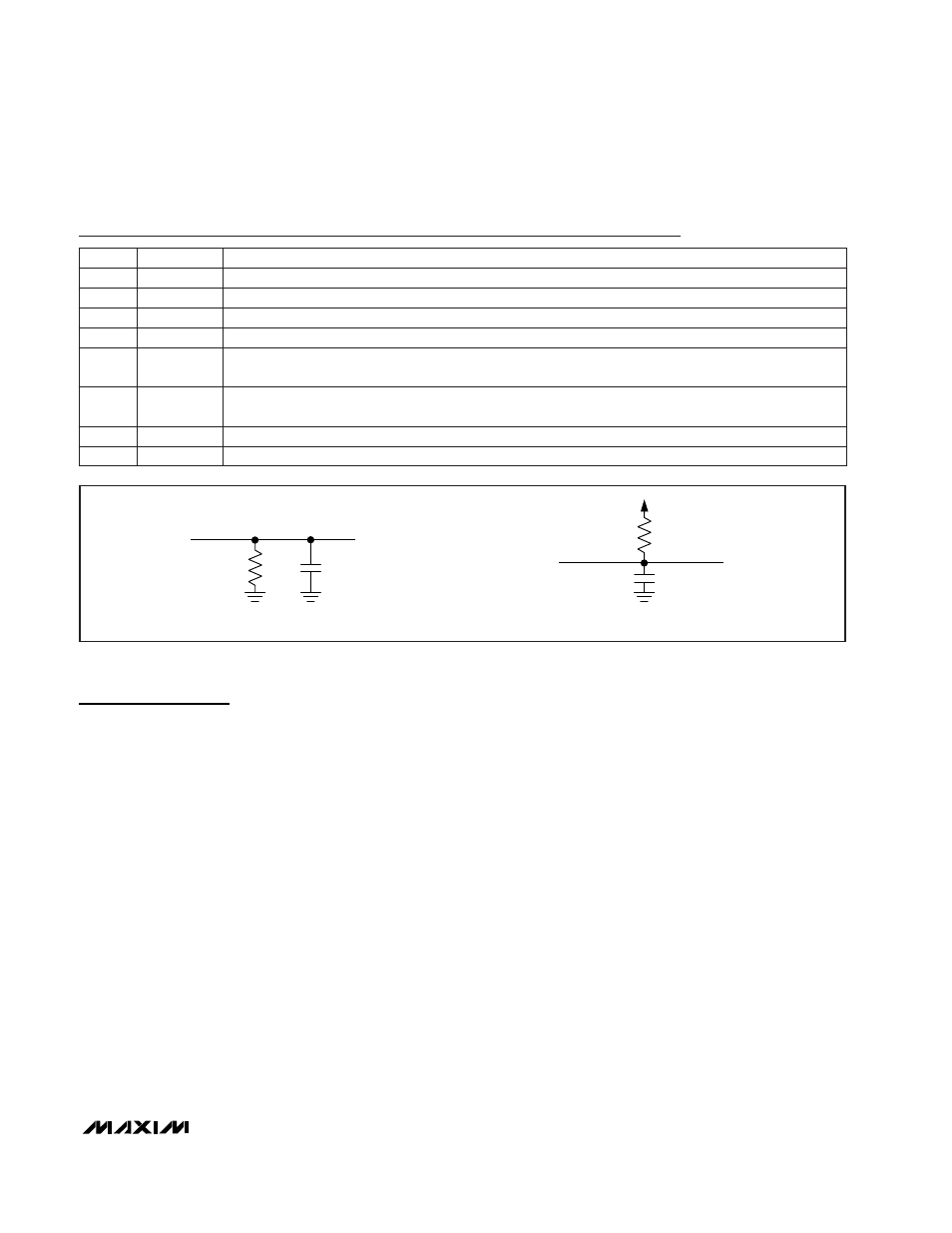
6k
C
L
DOUT
a) HIGH-Z TO V
0H
, V
0L
TO V
0H
, AND V
OH
TO HIGH-Z
6k
C
L
DOUT
GND
GND
V
DD
b) HIGH-Z TO V
0L
, V
0H
TO V
0L
, AND V
OL
TO HIGH-Z
Figure 1. Load Circuits for Enable and Disable Time
Pin Description
NAME
FUNCTION
1
V
DD
Positive Supply Voltage, +2.7V to +5.25V
2
CH0 (CH+)
Analog Input, MAX157: Single-Ended (CH0); MAX159: Differential (CH+).
PIN
3
CH1 (CH-)
Analog Input, MAX157: Single-Ended (CH1); MAX159: Differential (CH-).
4
GND
Analog and Digital Ground
8
SCLK
Serial Clock Input. DOUT changes on the falling edge of SCLK.
7
DOUT
Serial Data Output. Data changes state at SCLK’s falling edge. High impedance when CS/SHDN is high.
6
CS/SHDN
Active-Low Chip-Select Input, Active-High Shutdown Input. Pulling CS/SHDN high puts chip into
shutdown with a maximum current of 5µA.
5
REF
External Reference Voltage Input. Sets analog voltage range. Bypass with a 100nF capacitor close to the
part.