Rainbow Electronics MAX159 User Manual
Page 14
MAX157/MAX159
+2.7V, Low-Power, 2-Channel,
108ksps, Serial 10-Bit ADCs in 8-Pin µMAX
14
______________________________________________________________________________________
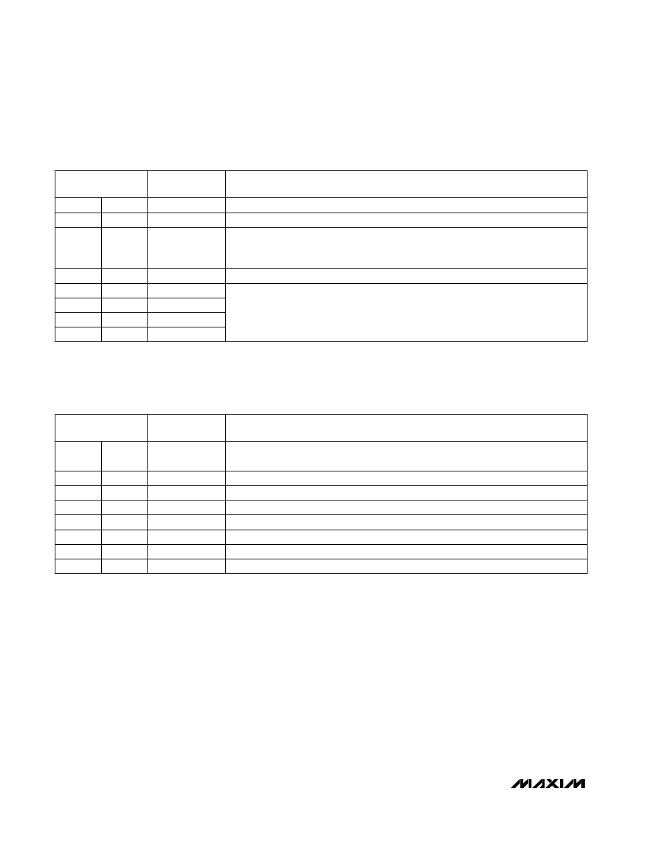
Table 3. Detailed SSPSTAT Register Content
Table 2. Detailed SSPCON Register Content
CONTROL BIT
MAX157/MAX159
SETTINGS
SYNCHRONOUS SERIAL PORT CONTROL REGISTER (SSPCON)
WCOL
Bit 7
X
Write Collision Detection Bit
SSPOV
Bit 6
X
Receive Overflow Detect Bit
SSPEN
Bit 5
1
Synchronous Serial Port Enable Bit
0: Disables serial port and configures these pins as I/O port pins.
1: Enables serial port and configures SCK, SDO and SCI pins as serial port pins.
CKP
Bit 4
0
Clock Polarity Select Bit. CKP = 0 for SPI master mode selection.
SSPM3
Bit 3
0
SSPM2
Bit 2
0
SSPM1
Bit 1
0
SSPM0
Bit 0
1
Synchronous Serial Port Mode Select Bit. Sets SPI master mode and selects
f
CLK
= f
OSC
/ 16.
X = Don’t care
X = Don’t care
D/A
CONTROL BIT
MAX157/MAX159
SETTINGS
SYNCHRONOUS SERIAL STATUS REGISTER (SSPSTAT)
Bit 5
X
Data Address Bit
P
Bit 4
X
Stop Bit
S
Bit 3
X
R/W
SMP
Bit 7
0
SPI Data Input Sample Phase. Input data is sampled at the middle of the data output
time.
CKE
Bit 6
1
SPI Clock Edge Select Bit. Data will be transmitted on the rising edge of the serial clock.
Bit 2
X
UA
Bit 1
X
BF
Bit 0
X
Start Bit
Buffer Full Status Bit
Update Address
Read/Write Bit Information