Rainbow Electronics MAX1637 User Manual
Page 2
MAX1637
Miniature, Low-Voltage,
Precision Step-Down Controller
2
_______________________________________________________________________________________
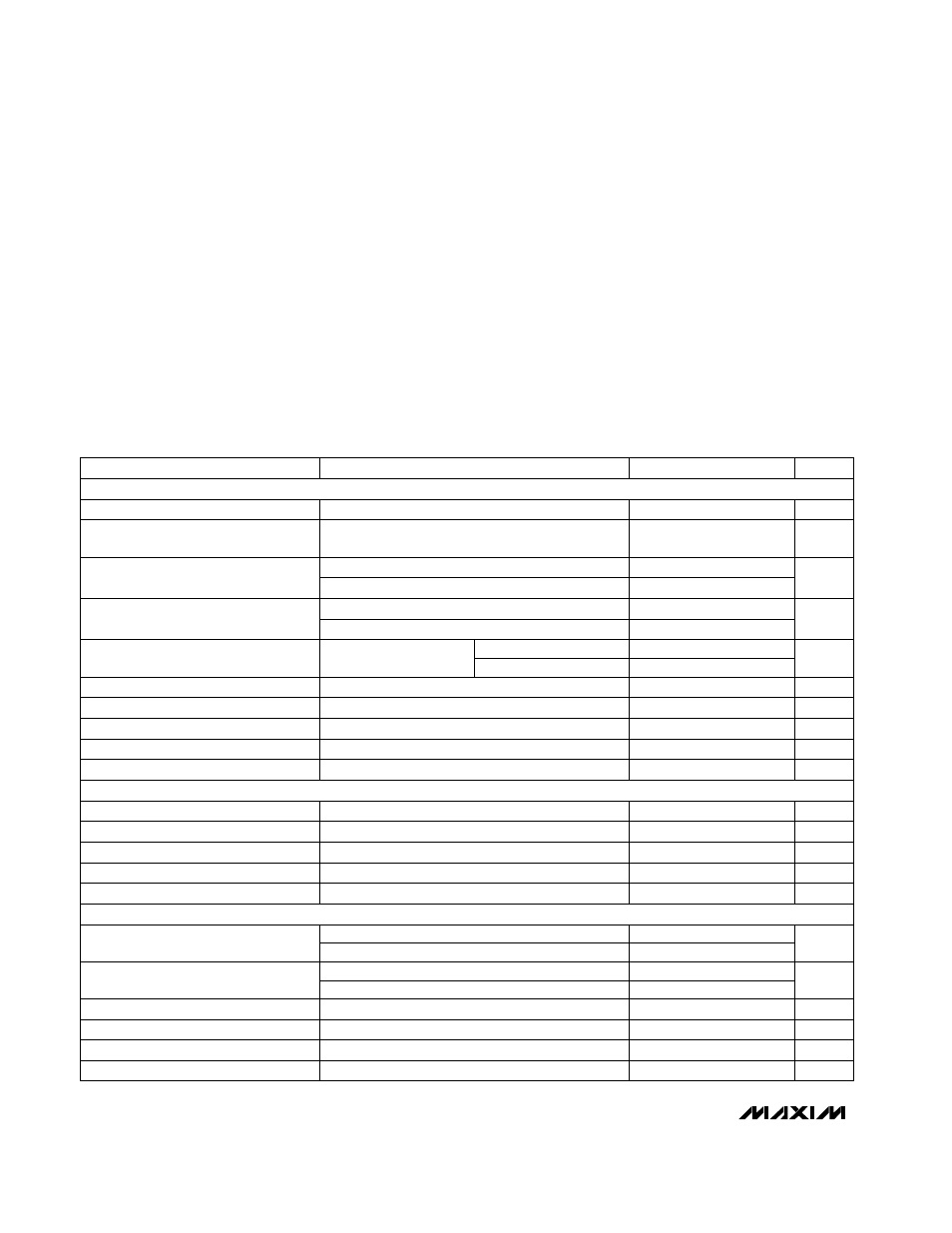
ABSOLUTE MAXIMUM RATINGS
ELECTRICAL CHARACTERISTICS
(Circuit of Figure 1, V
CC
= V
GG
= 5V, SYNC = V
CC
, I
REF
= 0mA,
T
A
= 0°C to +85°C
, unless otherwise noted. Typical values are at
T
A
= +25°C.)
Stresses beyond those listed under “Absolute Maximum Ratings” may cause permanent damage to the device. These are stress ratings only, and functional
operation of the device at these or any other conditions beyond those indicated in the operational sections of the specifications is not implied. Exposure to
absolute maximum rating conditions for extended periods may affect device reliability.
GND to PGND .............................................................+2V to -2V
LX, BST to GND......................................................-0.3V to +36V
BST, DH to LX...........................................................-0.3V to +6V
V
CC
, V
GG
, CSL, CSH, SHDN to GND.......................-0.3V to +6V
DL to GND..................................................-0.3V to (V
GG
+ 0.3V)
REF, SKIP, SYNC, CC to GND ...................-0.3V to (V
CC
+ 0.3V)
REF Output Current.............................................................20mA
REF Short-Circuit to GND ..............................................Indefinite
Operating Temperature Range ...........................-40°C to +85°C
Continuous Power Dissipation (T
A
= +70°C)
QSOP (derate 8.3mW/°C above +70°C) ......................667mW
Storage Temperature Range .............................-65°C to +160°C
Junction Temperature ......................................................+150°C
Lead Temperature (soldering, 10sec) .............................+300°C
SYNC = GND
SYNC = V
CC
FB tied to V
OUT
, 0mV < (CSH - CSL) < 80mV,
includes line and load regulation
V
CC
= 3.15V to 5.5V
REF load = 0µA to 50µA
V
CC
, V
GG
REF load = 0µA
Rising edge, hysteresis = 15mV
Rising edge, hysteresis = 15mV
SHDN = GND, V
CC
= V
GG
CSH - CSL = 0mV to CSH - CSL = 100mV
CSH - CSL
V
CC
= 5V
V
CC
= 3.3V
SHDN to full current limit, four levels
V
FB
= V
REF
CONDITIONS
170
200
230
Oscillator Frequency
kHz
270
300
330
mV
3
REF Line Regulation
mV
10
REF Load Regulation
V
1.080
1.100
1.120
REF Output Voltage
V
2.80
3.05
V
GG
Undervoltage Lockout Threshold
V
2.80
3.05
V
CC
Undervoltage Lockout Threshold
%
2
AC Load Regulation
mV
20
30
40
Idle-Mode Switchover Threshold
clocks
512
Soft-Start Ramp Time
nA
-50
50
FB Input Current
V
3.15
5.5
Input Voltage Range
µA
0.5
3
Shutdown Supply Current
V
1.080
1.100
1.120
Output Voltage
V
REF
5.5
Output Adjustment Range
V
V
REF
3.6
UNITS
MIN
TYP
MAX
PARAMETER
CSH > CSL
CSH < CSL
80
100
120
Current-Limit Threshold
mV
-145
-100
-55
Output not switching
1.5
2.5
Power Consumption
mW
1
1.75
SYNC = GND
SYNC = V
CC
ns
200
SYNC Input Pulse Width High
%
93
96
89
92
Maximum Duty Factor
(Note 1)
kHz
240
340
SYNC Input Frequency Range
ns
200
SYNC Input Rise/Fall Time
ns
200
SYNC Input Pulse Width Low
V
CC
= V
GG
= 5V
V
CC
= V
GG
= 3.3V
SMPS CONTROLLER
INTERNAL REFERENCE
OSCILLATOR